Method and apparatus for urea conditioning and injection control in a selective catalytic reduction system

a catalytic reduction and conditioning technology, applied in the direction of instruments, separation processes, other chemical processes, etc., can solve the problems of excessive amount of water present in the decomposition process, exhaust heat energy consumed in the decomposition process, exhaust energy consumed, etc., to achieve the effect of easing the delivery into the exhaus

Inactive Publication Date: 2015-10-08
VOLVO LASTVAGNAR AB
View PDF8 Cites 10 Cited by
  • Summary
  • Abstract
  • Description
  • Claims
  • Application Information

AI Technical Summary

Benefits of technology

[0003]In more recent years, this method has gained interest for use in mobile applications, for example, for use with engine exhaust in road vehicles, trains, and marine vessels. As mentioned, one version of the SCR process uses ammonia to convert NOx to nitrogen gas and water. To avoid carrying ammonia, some systems use an aqueous urea solution, which is stored on-board the vehicle in a supply tank. The aqueous urea solution is introduced into the exhaust flow, and in the presence of heat and water, decomposes into ammonia and CO2. The ammonia in the presence of an SCR catalyst heated to an operative temperature reduces NOx in the combustion gases to nitrogen and water vapor.
[0004]Aqueous urea is used (as opposed to other forms such as anhydrous ammonia) due to the stability of the solution, ease of delivery into exhaust, and relative ease in distribution to the vehicles and transport on the vehicles. Aqueous urea solution is commonly transported, stored, and used as a 32.5% urea solution because this concentration has the optimum freezing point suppression.

Problems solved by technology

When an aqueous urea solution is injected into an exhaust gas flow, the decomposition process consumes exhaust heat energy which would otherwise be available for heating the catalyst.
Additional water vapor is present in combustion exhaust, further adding to the excessive amount of water present to decompose urea.
The excess water in the 32.5% aqueous solution is a diluent in the NOx reduction reaction and also consumes exhaust energy to heat the water mass to the vapor state and then to the exhaust system temperature.
The use of exhaust energy for heating water cools the exhaust gas, making it more difficult to keep the SCR catalyst surface at its operating temperature.

Method used


Image

  • Method and apparatus for urea conditioning and injection control in a selective catalytic reduction system
  • Method and apparatus for urea conditioning and injection control in a selective catalytic reduction system
  • Method and apparatus for urea conditioning and injection control in a selective catalytic reduction system

Examples


Embodiment Construction

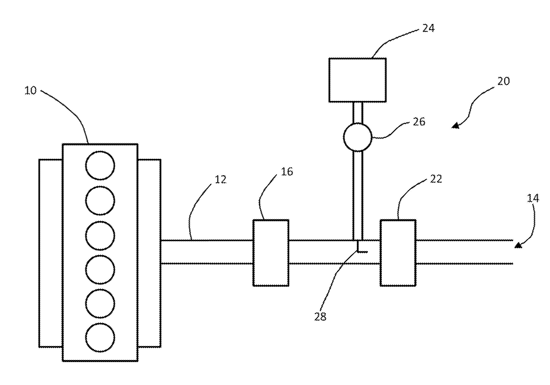
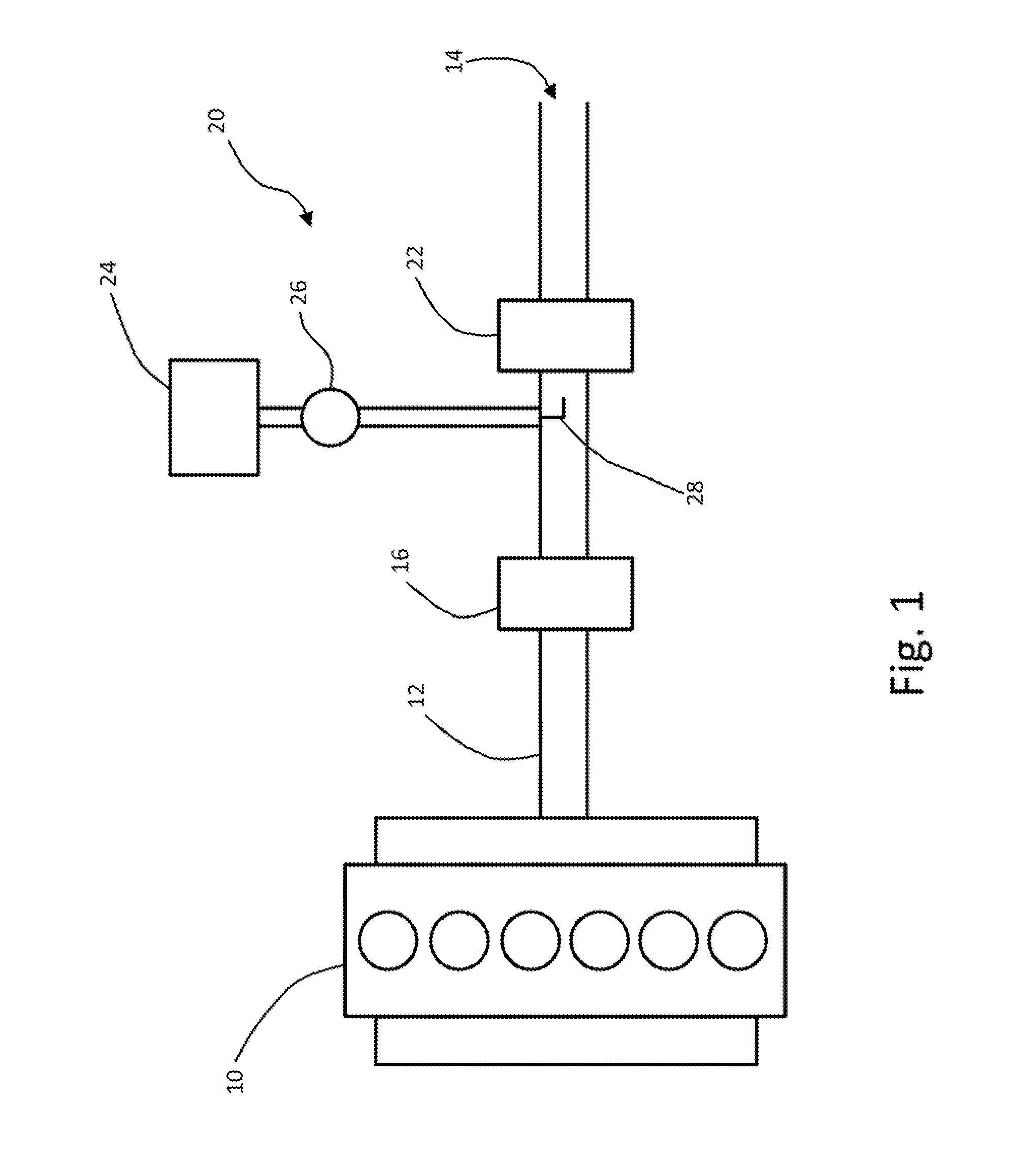
[0017]FIG. 1 illustrates schematically an SCR system incorporated in a diesel engine apparatus, as may be found on a heavy duty truck. Combustion in a diesel engine 10 produces exhaust gas, which is carried from the engine by an exhaust conduit 12 for release at an outlet 14 into the air. An exhaust aftertreatment system removes certain constituents of the exhaust gas prior to release to the environment. As an example of such a system, the illustrated aftertreatment system includes a particulate filter 16 to remove particulate matter (e.g., soot) from the exhaust. A selective catalytic reduction (SCR) apparatus, which includes an SCR catalyst 22 connected to the exhaust conduit 12 downstream of the particulate filter, converts nitrogen oxides in the exhaust gas to nitrogen and water. The SCR apparatus includes a storage tank 24 for holding a reactant in liquid form, in current use, an aqueous urea solution reactant. A pump 26 moves the aqueous urea solution to an injector 28, which ...


PUM


Abstract

An apparatus for conditioning an aqueous urea solution for injection in an engine exhaust treatment system, includes a urea solution conditioning tank having an inlet to receive an unconditioned urea solution and an outlet to deliver conditioned urea solution to an injection system, a sensor generating a signal indicating a concentration of urea in the tank, a heater for heating the urea solution in the tank and, an evaporation device for lowering the vapor pressure in the tank to remove evaporated water vapor from the tank.

Description

FIELD OF THE INVENTION[0001]The invention is directed to methods and apparatuses for preparing an aqueous urea reactant for injection in a selective catalytic reduction system for an engine exhaust.BACKGROUND AND SUMMARY[0002]Selective catalytic reduction (SCR) to eliminate oxides of nitrogen (NOx) from combustion exhaust gas has been used on stationary apparatuses, power plants and boilers for example, for many years. As is known, SCR works by reacting ammonia, or another reagent, and NOx in the presence of a catalyst to convert NOx to nitrogen gas and water vapor.[0003]In more recent years, this method has gained interest for use in mobile applications, for example, for use with engine exhaust in road vehicles, trains, and marine vessels. As mentioned, one version of the SCR process uses ammonia to convert NOx to nitrogen gas and water. To avoid carrying ammonia, some systems use an aqueous urea solution, which is stored on-board the vehicle in a supply tank. The aqueous urea solu...

Claims


Application Information

Patent Timeline
Patent Type & Authority Applications(United States)
IPC IPC(8): B01D53/94
CPCB01D53/9409F01N3/208F01N2610/02F01N2610/105F01N2900/1818F01N3/2066F01N2610/1406F01N2900/1808F01N2900/1814F01N2610/142Y02E20/14Y02A50/20Y02T10/12
Inventor BROOKS, JEFFREY A.BERGH, PATRIK
Owner VOLVO LASTVAGNAR AB
Why Eureka
Try Eureka