Solid-liquid oil-water separation device for kitchen waste

An oil-water separation device, a technology for kitchen waste, applied in the directions of liquid separation, immiscible liquid separation, separation methods, etc., can solve problems such as difficult cleaning, odor emission of collection devices, breeding of bacteria and mosquitoes, etc. The effect of facilitating transparency and reducing moisture content

Active Publication Date: 2020-03-17
HARBIN ONTOP DRAINAGE EQUIP MFG
View PDF9 Cites 1 Cited by
  • Summary
  • Abstract
  • Description
  • Claims
  • Application Information

AI Technical Summary

Problems solved by technology

[0006] The present invention aims at the present kitchen garbage collection device, which is difficult to clean after the filter holes of the filter pool or the filter bucket are clogged, and the filter pool cannot be disassembled or the filter bucket is inconvenient to disassemble; The space in the garbage storage room, the problem of easy pollution of the environment during secondary dumping and transportation, and the problem that the oil-water separation device cannot judge the thickness of the waste oil layer in the oil collection area, and the timing of oil discharge cannot be grasped, and the current kitchen waste collection Most of the food residue discharge ports of the device are open. When pouring food residue into the garbage collection device, it is easy to cause problems such as garbage splashing, odor in the collection device, and bacteria and mosquitoes. A solid-liquid solution for kitchen waste is proposed. Oil-water separation device

Method used


Image

  • Solid-liquid oil-water separation device for kitchen waste
  • Solid-liquid oil-water separation device for kitchen waste
  • Solid-liquid oil-water separation device for kitchen waste

Examples


specific Embodiment approach 1

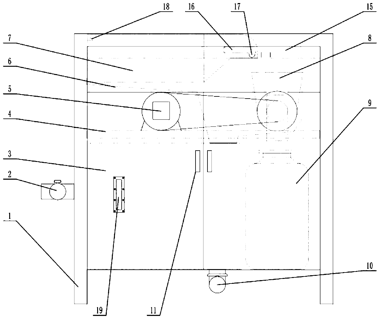
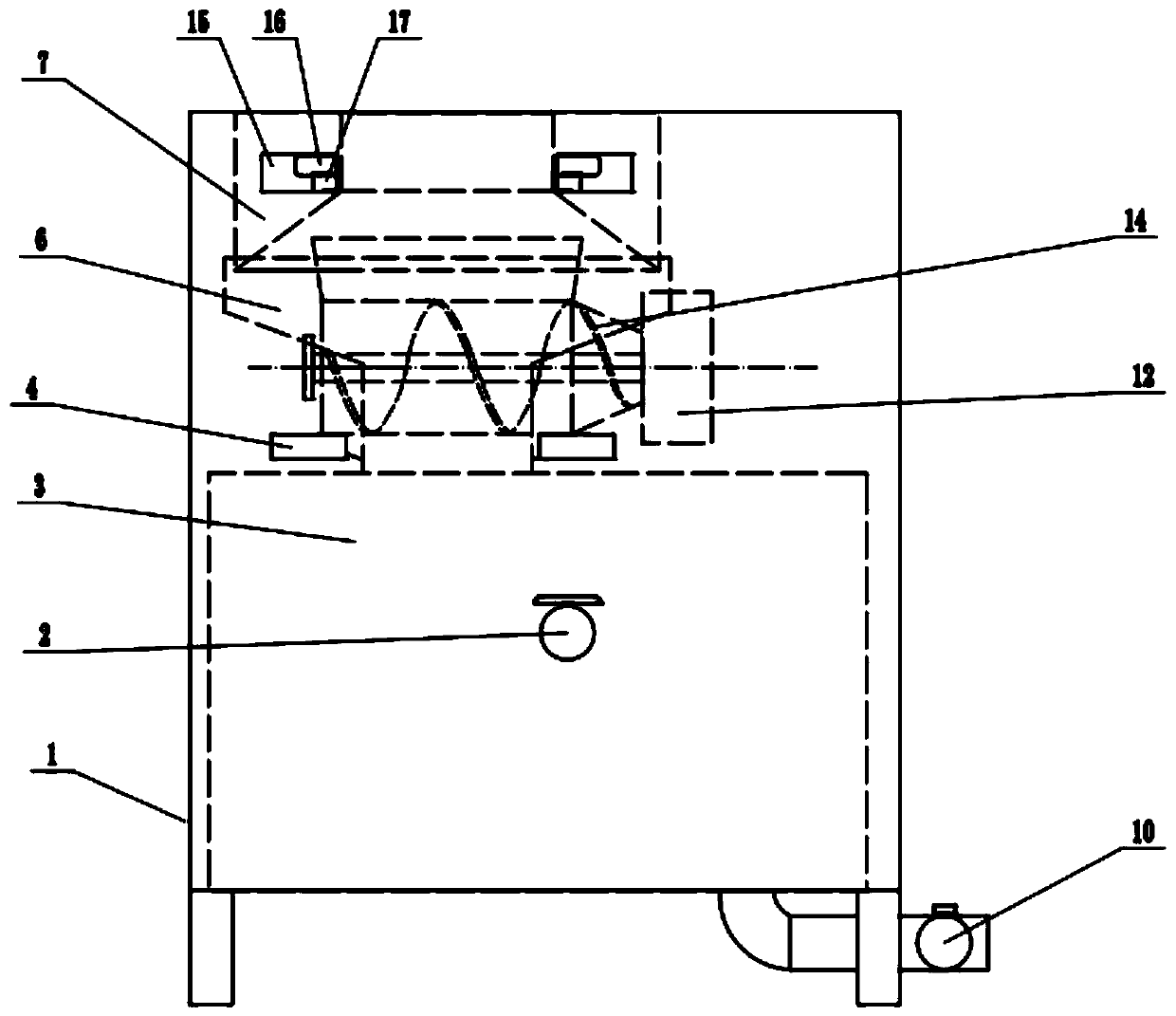
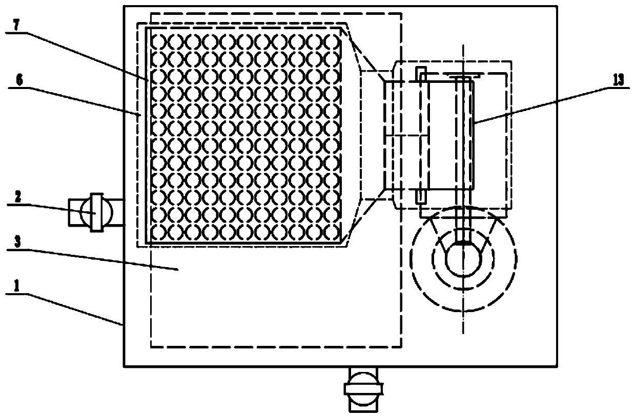
[0043] Specific implementation mode one: see Figure 1-13 This embodiment will be described. A food waste solid-liquid oil-water separation device described in this embodiment includes a box body 1, an oil-water separator 3, a fixed bracket 4, a driving device 5, a residual liquid collector 6, a solid-liquid separator 7, and a residue collection port 8 , a residue collection container 9, a residue discharge port 12 and a screw extrusion device 14; a solid-liquid separator 7 is installed on the top of the casing 1, and a residual liquid collector 6 is installed below the solid-liquid separator 7, The below of described raffinate collector 6 is equipped with fixed support 4, and described fixed support 4 is fixed with driving device 5 and screw extruding device 14, and described driving device 5 drives screw extruding device 14 to rotate, and described driving device 5 includes a drive motor and a reducer, driven by a belt, an oil-water separator 3 is installed under the screw ...


PUM


Abstract

The invention provides a solid-liquid oil-water separation device for kitchen waste. A solid-liquid separator is mounted at the upper part in a box body of the device; a residual liquid collector is mounted below the solid-liquid separator; a driving device drives a spiral extrusion device to rotate; an oil-water separator is mounted below the spiral extrusion device; a residue collecting openingis formed above the spiral extrusion device; a residue discharge port is formed in the end, a residual liquid outlet is formed below the end, the residue collecting opening is located below an outletof the solid-liquid separator, the residual liquid outlet is connected with a residual liquid collector, a water outlet of the residual liquid collector is connected with a water inlet of the oil-water separator, and a residue collection container is installed below the residue discharge port. According to the invention, he problems are solved that for an existing kitchen waste collecting device,filtering holes of a filtering pool or a filtering hopper are not easy to clean after being blocked, and the filtering pool cannot be detached or the filtering hopper is inconvenient to detach; and the filtered garbage is high in water content, and easily ferments to generate peculiar smell to pollute the space of a garbage storage room, and the environment is easily polluted during secondary transferring and transportation.

Description

technical field [0001] The invention mainly relates to the classification and recycling of kitchen waste, in particular to a solid-liquid oil-water separation device for kitchen waste, which belongs to the technical field of oil-water separation devices. Background technique [0002] At present, garbage classification is the general trend. The service personnel of commercial catering establishments are the operators of food waste classification, and the existing operation method is that the service personnel pour the food waste into the garbage covered with garbage bags, and collect it in the garbage bin When it is full, push the garbage can to the recycling station, and the recyclers will recycle and transport it uniformly. During the dumping process, the juice in the garbage bag will pollute the dumping site. In addition, there is also a kitchen waste recycling device on the market, which mostly uses fixed A filter tank or a solid-liquid separator with a fixed shaft is use...

Claims


Application Information

Patent Timeline
IPC IPC(8): B09B3/00C02F1/40B01D17/02B30B9/14
CPCC02F1/40B01D17/02B30B9/14B09B3/00B09B2101/02
Inventor 祝丹梁滨董学武孟丽娟许擎峰贾东光
Owner HARBIN ONTOP DRAINAGE EQUIP MFG
Why Eureka
Try Eureka