Plate deburring equipment

A deburring and equipment technology, applied in metal processing equipment, grinding/polishing equipment, grinding machines, etc., can solve inconvenience, complexity and other problems, achieve the effect of increasing friction, increasing friction factor, and improving deburring efficiency

Inactive Publication Date: 2020-03-17
湖北乔木森家具有限公司
View PDF1 Cites 5 Cited by
  • Summary
  • Abstract
  • Description
  • Claims
  • Application Information

AI Technical Summary

Problems solved by technology

The workpieces in the rotating tank will rotate together with the rotation of the rotating tank. Through the contact between the workpieces and the contact between the workpiece and the side wall of the rotating tank, the function of deburring is realized, which eliminates manual operation and improves the work efficiency. Efficiency, when removing burrs in the above-mentioned patents, due to the complicated device, it may cause inconvenience if the burrs need to be removed temporarily on the construction site

Method used


Image

  • Plate deburring equipment
  • Plate deburring equipment
  • Plate deburring equipment

Examples


Embodiment 1

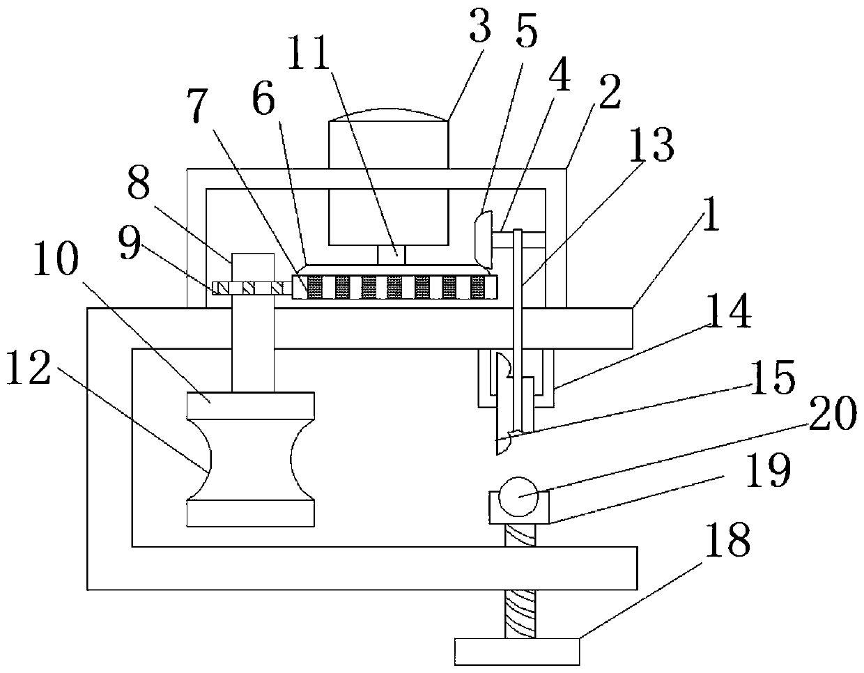
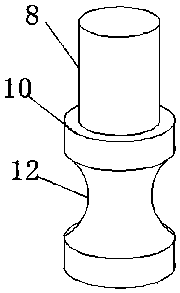
[0027] refer to Figure 1-3 , a plate deburring equipment, including a U-shaped groove 1, a power chamber 2 is welded to the top of the U-shaped groove 1, an air motor 3 is welded to the top of the power chamber 2, and a rotary column 11 is welded to the output end of the air motor 3 The bottom end of the rotating column 11 is welded with the first bevel gear 6, the bottom end of the first bevel gear 6 is welded with the first gear 7, one side of the power chamber 2 is connected with the rotating rod 4 through the rotation of the rotating shaft, and the top end of the rotating rod 4 is welded There is a second bevel gear 5, the first bevel gear 6 meshes with the second bevel gear 5, the top of the U-shaped groove 1 is connected to the rotating rod 8 through the rotating shaft at the inside of the power chamber 2, and the top of the rotating rod 8 is welded with the second bevel gear. Two gears 9, and the first gear 7 and the second gear 9 are meshed, the bottom end of the rota...

Embodiment 2

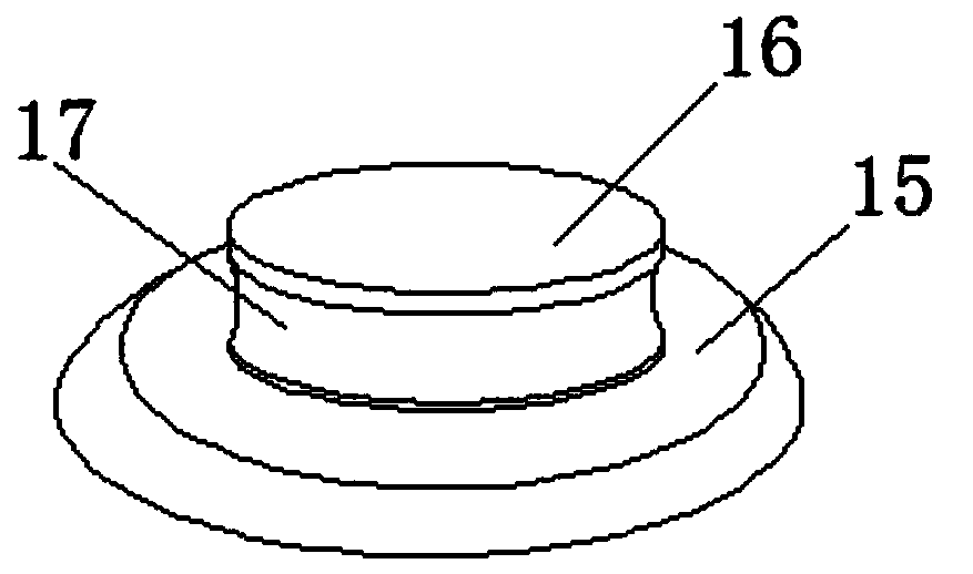
[0032] refer to Figure 4 , a plate deburring equipment. Compared with Example 1, in order to improve the friction between the arc-shaped rubber disc and the plate, the arc-shaped rubber disc 15 is provided with an anti-slip groove 21 outside. When the arc-shaped rubber disc 15 When the disc 15 is bent, the anti-slip groove 21 on the arc-shaped rubber disc 15 increases the friction factor on the surface of the plate, improves the friction force of the arc-shaped rubber disc 15 when bending, and makes the arc-shaped grinding groove 12 exert pressure on the plate at all times .

[0033] Working principle: Turn on the air motor 3, the air motor 3 drives the rotating column 11 to rotate, the rotating column 11 drives the first bevel gear 6, the second bevel gear 5, the first gear 7, and the second gear 9 mesh with each other to drive grinding When the column 10 grinds the edge of the plate, it drives the whole device to move under the rotation of the rotary block 16. At the same ...


PUM


Abstract

The invention discloses plate deburring equipment comprising a U-shaped groove. The top end of the U-shaped groove is fixedly connected with a power cabin with the top end fixedly connected with a pneumatic motor, and the output end of the pneumatic motor is fixedly connected with a rotating column; the bottom end of the rotating column is fixedly connected with a first bevel gear with the bottomend fixedly connected with first gears, and one side of the power cabin is rotatably connected with a rotating rod through a rotating shaft; the top end of the rotating rod is fixedly connected with asecond bevel gear, and the first bevel gear is engaged with the second bevel gear; the part, in the power cabin, of the top end of the U-shaped groove is rotatably connected with the rotating rod through the rotating shaft, and the top end of the rotating rod is fixedly connected with a second gear; and the first gears are engaged with the second gear, and the bottom end of the rotating rod is fixedly connected with a grinding column. Compared with an existing device, the plate deburring equipment has the advantages that the equipment is moved along the edge of a plate while the gears are driven by the pneumatic motor to engage mutually and the equipment is driven to grind the plate; and the deburring efficiency of the equipment is improved.

Description

technical field [0001] The invention relates to the technical field of building material equipment, in particular to a plate deburring equipment. Background technique [0002] With the rapid development of the market economy, automation equipment is becoming more and more popular. People mostly use large-scale machinery to deal with the edge burrs of some building panels, which are inconvenient to carry. There are also some hand-held deburring equipment on the market. The technical requirements for the staff are high, and errors are prone to occur, which may lead to a reduction in the quality of the board. [0003] After searching, the Chinese patent application number is CN201820107905.2, which discloses a deburring equipment, which involves the field of mechanical processing technology. The technical points of the scheme are: a deburring equipment, including a frame, a rotating tank, and a driving device The rotating tank is rotatably connected to the frame, the driving d...

Claims


Application Information

Patent Timeline
Patent Type & Authority Applications(China)
IPC IPC(8): B24B9/18B24B55/00B24B47/14
CPCB24B9/18B24B47/14B24B55/00
Inventor 程燃
Owner 湖北乔木森家具有限公司
Why Eureka
Try Eureka