Dynamic Component Matching in Integrated Circuits

A dynamic component matching and circuit technology, which is applied to parts of thermometers, thermometers with directly heat-sensitive electric/magnetic components, programmable logic circuit devices, etc., can solve inaccurate temperature measurement, large area, consumption, etc. question

Active Publication Date: 2022-04-05
XILINX INC
View PDF16 Cites 0 Cited by
  • Summary
  • Abstract
  • Description
  • Claims
  • Application Information

AI Technical Summary

Problems solved by technology

This temperature sensing circuit consumes a large area due at least in part to the matching requirements of the 1:N current bias source
Mismatches between diode-connected BJTs can lead to inaccurate temperature measurements

Method used


Image

  • Dynamic Component Matching in Integrated Circuits
  • Dynamic Component Matching in Integrated Circuits
  • Dynamic Component Matching in Integrated Circuits

Examples


Embodiment Construction

[0016] Various features are described herein with reference to the accompanying drawings. It should be noted that the figures may or may not be drawn to scale and that elements of similar structure or function may be represented by like reference numerals throughout the figures. It should be noted that the drawings are only intended to facilitate the description of the features. They are not intended to be exhaustive or to limit the scope of the claimed invention. In addition, an illustrated example need not have all of the aspects or advantages shown. An aspect or an advantage described in connection with a particular example is not necessarily limited to that example, and can be applied to other examples even if not explicitly described or illustrated as such.

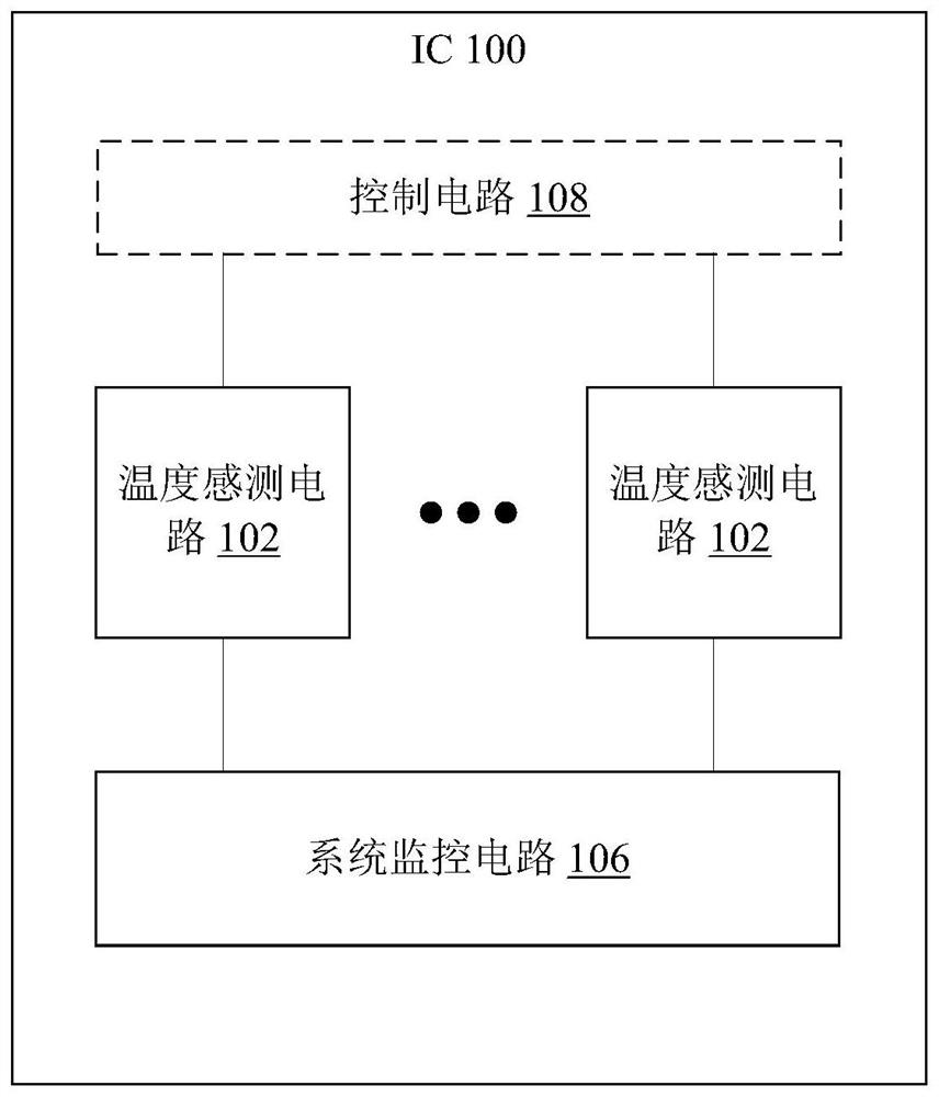
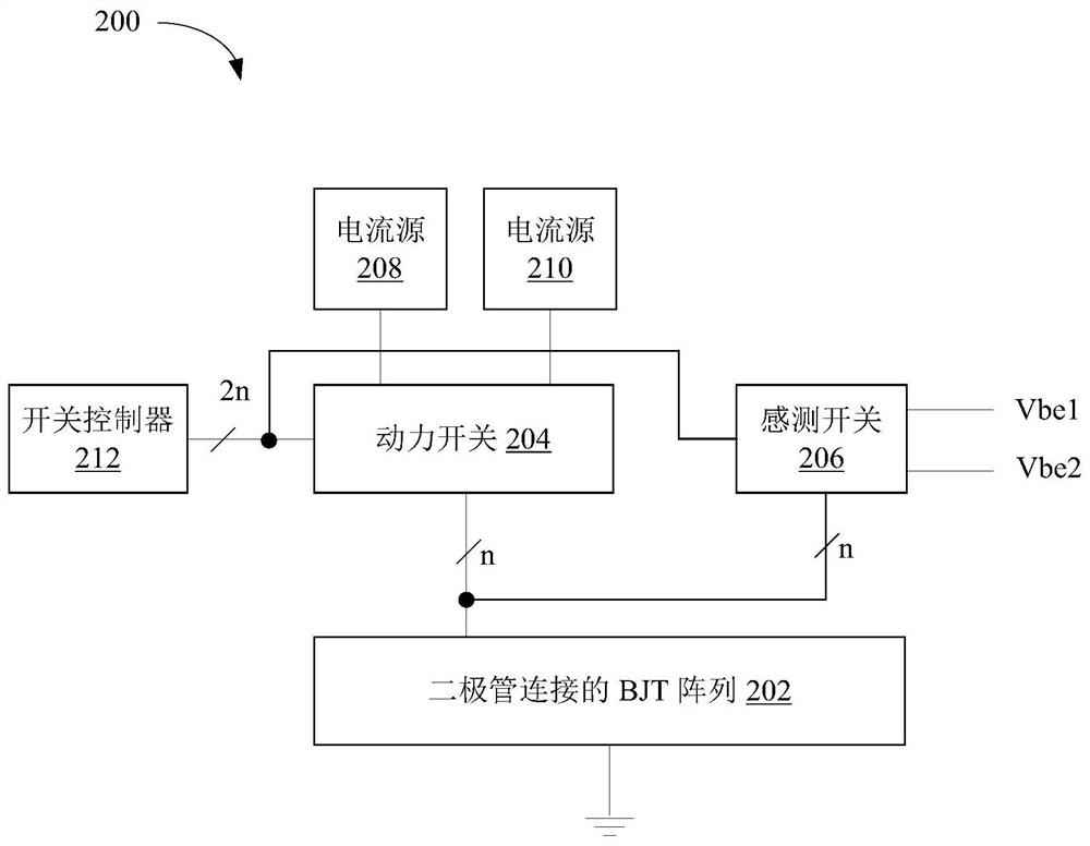
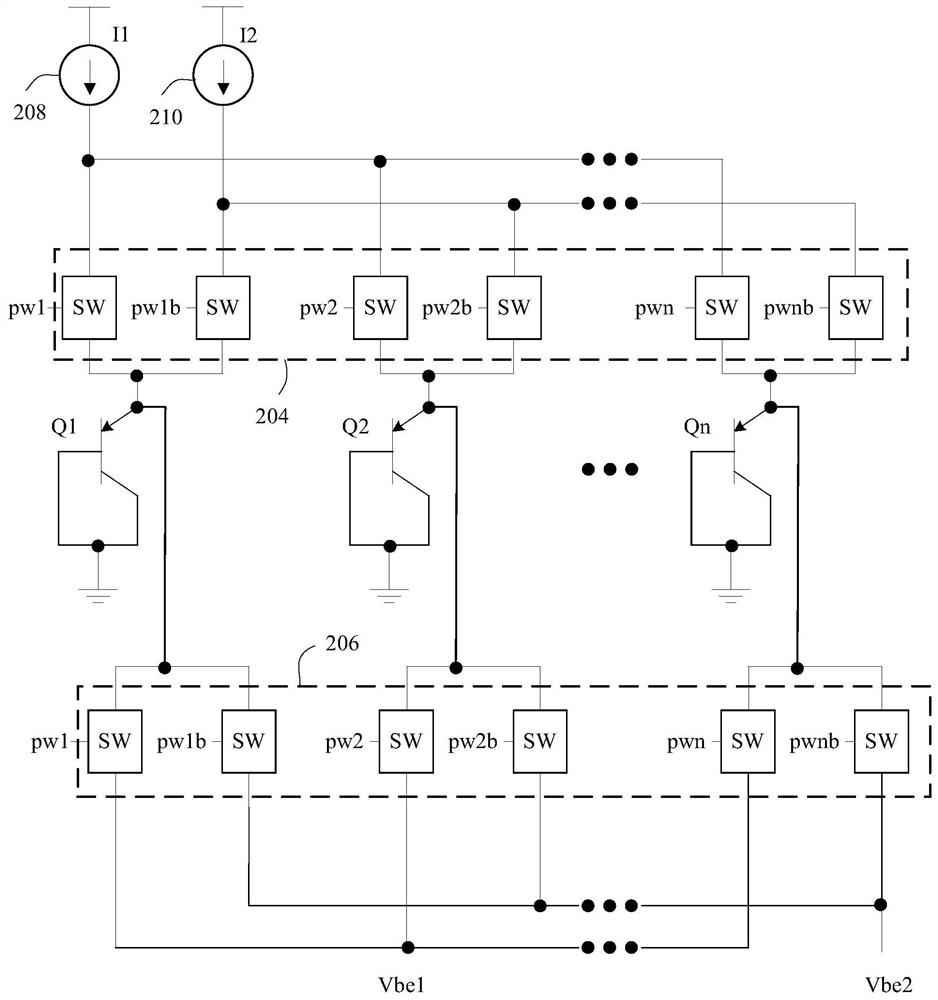
[0017] Dynamic component matching techniques in integrated circuits (ICs) will be described below. In one example, a dynamic element matching (DEM) circuit includes an array of bipolar junction transistors (BJTs) ...


PUM


Abstract

An example dynamic element matching (DEM) circuit includes: a plurality of bipolar junction transistors (BJTs) (202), each of the plurality of BJTs having a base terminal and a collector terminal coupled to electrical ground; a plurality of power switch pairs (204), each power switch pair coupled to an emitter of a respective one of the plurality of BJTs; a plurality of sensing switch pairs (206), each sensing switch pair being respectively coupled to a plurality of BJTs The emitter of each of the BJTs, the first switch of each sense switch pair is coupled to the first node (Vbel), and the second switch of each sense switch pair is coupled to the second node (Vbe2); a first current source (208) coupled to the first switch in each power switch pair; and a second current source (210) coupled to the second switch in each power switch pair .

Description

technical field [0001] Examples of the present disclosure relate generally to electronic circuits and, more particularly, to dynamic component matching in integrated circuits (ICs). Background technique [0002] Temperature sensing circuitry is an important function associated with integrated circuits (ICs), such as large systems-on-chip (SoCs), field-programmable gate arrays (FPGAs), and similar devices. A temperature sensing circuit is implemented by driving a first diode-connected BJT with a unit current and driving a second diode-connected BJT with a multiple of the unit current. The second diode-connected BJT mates with the first diode-connected BJT. That is, a 1:1 BJT array is driven with a 1:N current bias, where N is a positive integer greater than 1. Such temperature sensing circuitry consumes significant area due at least in part to the matching requirements of the 1:N current bias sources. Mismatches between diode-connected BJTs can cause inaccurate temperature...

Claims


Application Information

Patent Timeline
Patent Type & Authority Patents(China)
IPC IPC(8): G01K7/01
CPCG01K1/026G01K7/015H03K19/00307H03K19/017581G01K7/01
Inventor U·R·卡马斯P·凯利J·K·詹宁斯
Owner XILINX INC
Why Eureka
Try Eureka