Light transmittance adjusting device and lighting system

A light transmittance and adjustment device technology, which is applied in the direction of exposure devices, optics, and optomechanical equipment in the photoplate making process, can solve the problems of adjusting resolution, unable to reduce the size of the space, and occupying a large space, so as to achieve high light transmission The effect of rate adjustment resolution, continuous light transmittance adjustment, and simple structure

Active Publication Date: 2020-03-20
SHANGHAI MICRO ELECTRONICS EQUIP (GRP) CO LTD
View PDF4 Cites 0 Cited by
  • Summary
  • Abstract
  • Description
  • Claims
  • Application Information

AI Technical Summary

Problems solved by technology

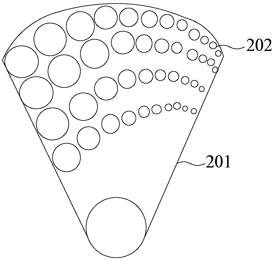
figure 1 The light transmittance range of the adjustment body shown is limited, the upper limit is only about 50%. In addition, since the multiple circular holes 202 are separated from each other, continuous transmittance adjustment cannot be realized, and it cannot be realized in a small space size. Higher light transmittance adjusts resolution
In order to solve the above problems, an optical compensator is proposed in the prior art. The optical compensator can change the light transmittance by using the different light transmittance of the lens at different angles. However, due to the need to use two lenses, the optical compensation The space occupied by the device along the optical axis is large, the structure is complex, and the cost is high due to the difficulty of the mirror coating process

Method used


Image

  • Light transmittance adjusting device and lighting system
  • Light transmittance adjusting device and lighting system
  • Light transmittance adjusting device and lighting system

Examples


Embodiment Construction

[0023] The present invention will be further described in detail below in conjunction with the accompanying drawings and embodiments. It should be understood that the specific embodiments described here are only used to explain the present invention, but not to limit the present invention. In addition, it should be noted that, for the convenience of description, only parts related to the present invention are shown in the drawings but not all content. Before discussing the exemplary embodiments in more detail, it should be mentioned that some exemplary embodiments are described as processes or methods depicted as flowcharts. Although the flowcharts describe various operations (or steps) as sequential processing, many of the operations may be performed in parallel, concurrently, or simultaneously. In addition, the order of operations can be rearranged. The process may be terminated when its operations are complete, but may also have additional steps not included in the figure...


PUM


Abstract

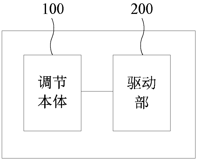
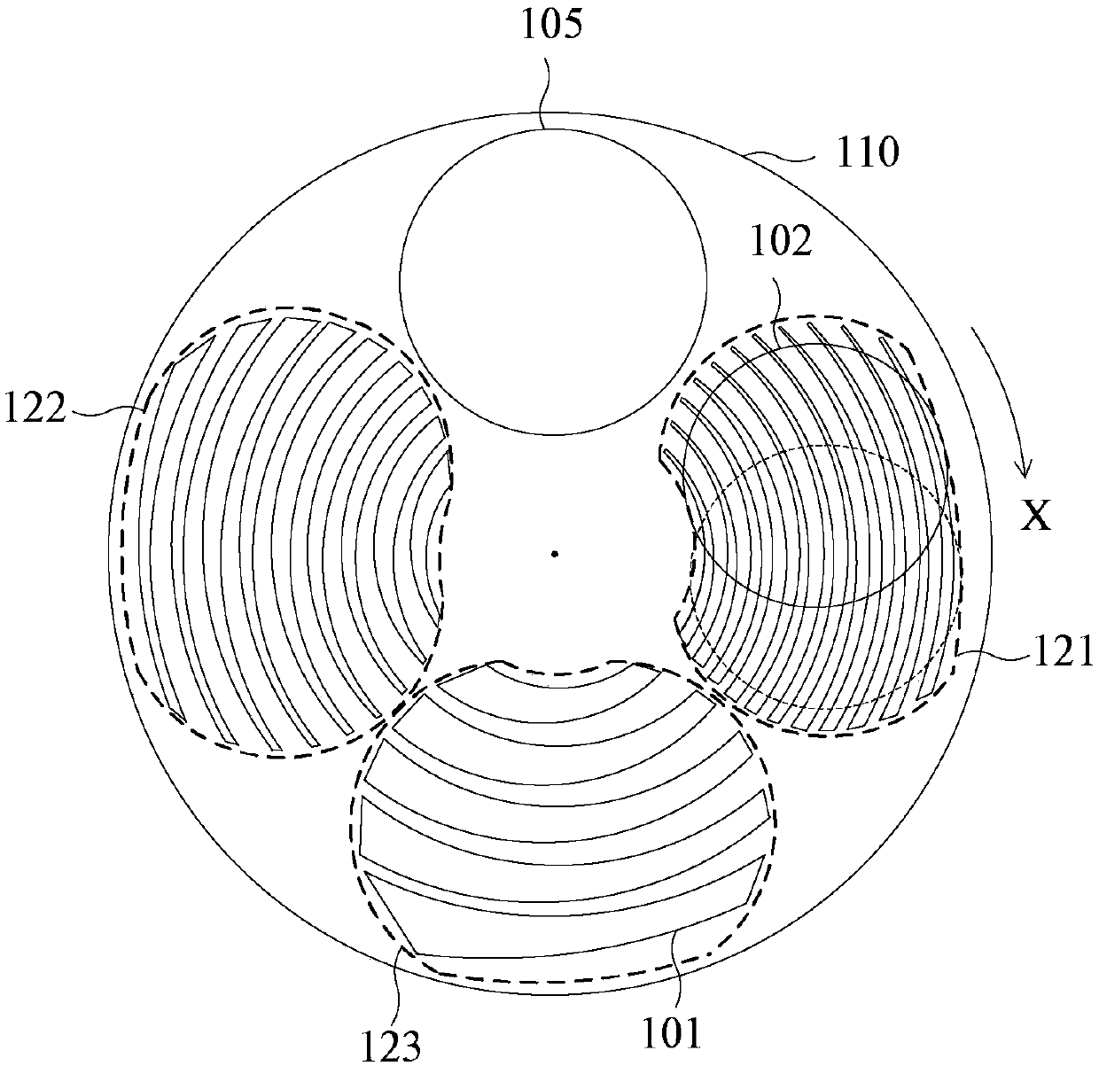
The invention discloses a light transmittance adjusting device and a lighting system. The light transmittance adjusting device comprises an adjusting body and a driving part connected with the adjusting body. The driving part is used for driving the adjusting body to move in the first direction or in the direction opposite to the first direction, wherein the adjusting body comprises a substrate and at least one light adjusting unit, the light adjusting unit comprises a plurality of grooves which are formed in the substrate and distributed at equal intervals, and the grooves extend in the firstdirection; an adjusted light spot falls in an area where the light adjusting unit is located; and in the first direction, the width of the groove is gradually increased or decreased. According to thetechnical scheme, the light transmittance adjusting device is simple in structure and low in cost, continuous light transmittance adjustment is achieved, and the high light transmittance adjusting resolution can be achieved through the adjusting body with the small space size.

Description

technical field [0001] Embodiments of the present invention relate to light transmittance adjustment technology, and in particular to a light transmittance adjustment device and an illumination system. Background technique [0002] The lighting system is an important part of the lithography machine equipment. In order to avoid the different powers of at least two mercury lamps in the lighting system from affecting the accuracy of the lithography machine, it is necessary to use a light transmittance adjustment device to adjust the light emitted by each mercury lamp. [0003] figure 1 It is a structural schematic diagram of the adjusting body in the light transmittance adjusting device in the prior art. like figure 1 As shown, the adjusting body includes a fan-shaped base plate 201 and a plurality of circular holes 202 with different diameters formed on the fan-shaped base plate 201 , and the fan-shaped base plate 201 can rotate around its fan-shaped center. for figure 1 A...

Claims


Application Information

Patent Timeline
Patent Type & Authority Applications(China)
IPC IPC(8): G03F7/20
CPCG03F7/70058G03F7/70141G03F7/7015
Inventor 章富平王彩红湛宾洲郁健周伟
Owner SHANGHAI MICRO ELECTRONICS EQUIP (GRP) CO LTD
Why Eureka
Try Eureka