Pin-free positioning automatic expansion and shrinkage drilling production method

A production method and technology for positioning holes, which are used in electrical components, printed circuit manufacturing, printed circuits, etc., can solve problems such as drilling deviation of production boards, and achieve the effect of improving alignment accuracy and reducing the scrap rate of drilling deviation.

Inactive Publication Date: 2020-03-20
YIXING SILICON VALLEY ELECTRONICS TECH
View PDF7 Cites 6 Cited by
  • Summary
  • Abstract
  • Description
  • Claims
  • Application Information

AI Technical Summary

Problems solved by technology

[0005] In order to solve the problem that the difference in expansion and contraction of the production board leads to the deviation of the drilling hole, the present invention provides a new production operation method for the expansion and contraction of the drilling hole

Method used


Image

  • Pin-free positioning automatic expansion and shrinkage drilling production method
  • Pin-free positioning automatic expansion and shrinkage drilling production method

Examples


Embodiment 1

[0016] The overall process of the production method of automatic expansion and contraction drilling without Pin positioning: area division → area symbol design → X-Ray punching → CCD drilling, the specific steps are as follows:

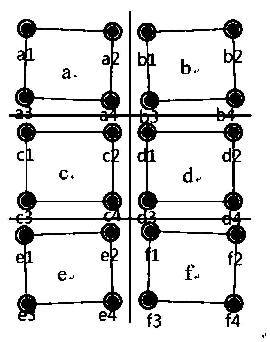
[0017] Step 1: When the production board has alignment requirements (such as alignment requirements ≤ 6mil), it is divided into regions. Such as figure 2 In this embodiment, the production board is divided into six areas a, b, c, d, e, and f, and the smaller the area division, the higher the alignment accuracy.

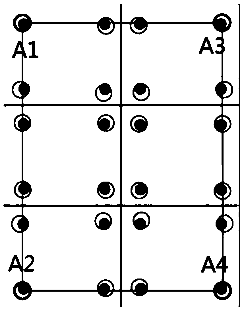
[0018] Step 2: Add a symbol design to the inner layer graphics at the four corners of each area (symbol is the target designed in the inner layer PCB, the target is the copper pad, and the design is on the short side, a total of 4, X-Ray can recognize the copper pad and place it on the copper pad The position of the pad is punched), and then through the pressing process X-Ray to identify and punch, and the symbol design position is punched ...


PUM


Abstract

The invention discloses a Pin-free positioning automatic expansion and shrinkage drilling manufacturing method. The production plate is divided into a plurality of areas; each area is independently provided with a positioning hole; the CCD camera is used for grabbing and identifying the positioning hole in each area in the plate; corresponding drilling expansion and shrinkage ranges are given according to actual lamination expansion and shrinkage values of all areas, so that one-to-one correspondence between the drilling expansion and shrinkage ranges of different layers and actual expansion and shrinkage is achieved, and the rejection rate of drilling deviation caused by the difference between lamination expansion and shrinkage and actual production plates is reduced.

Description

technical field [0001] The invention relates to the technical field of PCB production, in particular to a drilling method. Background technique [0002] In the PCB design, the design of the alignment test pattern will be added in the board, and the purpose of monitoring the quality of the entire board can be achieved by monitoring the quality of the alignment test pattern. As the distance between the holes in the alignment test pattern and the copper or the holes in the board and the copper is getting smaller and smaller, and it is getting closer to the limit design, the conventional drilling expansion and contraction operation method can no longer meet the demand. [0003] After lamination, the X-Ray punching process is based on the principle of substrate light transmission, copper opacity and X-Ray penetration, and a special optical target is set in the inner layer of the production board. By grabbing the center of the target, drilling After exiting the process positionin...

Claims


Application Information

Patent Timeline
Patent Type & Authority Applications(China)
IPC IPC(8): H05K3/00
CPCH05K3/0047H05K3/005
Inventor 夏许冬姚育松
Owner YIXING SILICON VALLEY ELECTRONICS TECH
Why Eureka
Try Eureka