Supercharge Your Innovation With Domain-Expert AI Agents!

Waste gas treatment device for power plant

A waste gas treatment device and waste gas treatment technology, which are used in gas treatment, transportation and packaging, dispersed particle filtration, etc., can solve the problems of no secondary filtration, low filtration efficiency, low adsorption efficiency, etc., so as to improve treatment efficiency and treatment efficiency. effect, high cleanliness, and the effect of improving the filtration effect

Inactive Publication Date: 2020-03-24
华电阜康发电有限公司
View PDF5 Cites 4 Cited by
  • Summary
  • Abstract
  • Description
  • Claims
  • Application Information

AI Technical Summary

Problems solved by technology

Most of the existing exhaust gas treatment devices are filtered through the filter device, and then supplemented with chemicals for treatment, but this method makes the filtration efficiency low during the treatment process, without secondary filtration, and the adsorption efficiency during the adsorption process is also low. not tall

Method used


Image

  • Waste gas treatment device for power plant
  • Waste gas treatment device for power plant
  • Waste gas treatment device for power plant

Examples


Embodiment 1

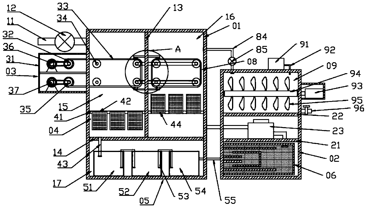
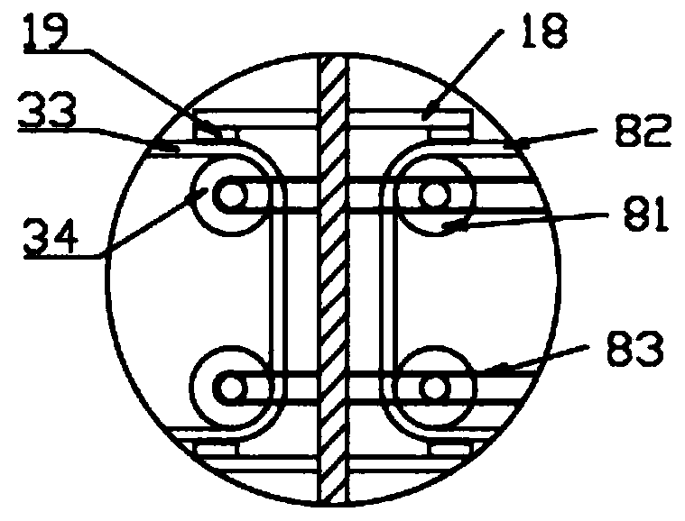
[0027] see Figure 1~4 , in an embodiment of the present invention, an exhaust gas treatment device for a power plant includes a first exhaust gas treatment box 01 and a second exhaust gas treatment box 02, and the first exhaust gas treatment box 01 communicates with the second exhaust gas through a third gas duct 55 The treatment box 02 is connected to transfer the gas in the first exhaust gas treatment box 01 to the second exhaust gas treatment box 02. The first exhaust gas treatment box 01 is used to treat the exhaust gas, and the second exhaust gas treatment box 02 is used to treat At the same time, the second exhaust gas treatment box 02 communicates with the first exhaust gas treatment box 01 through the second gas duct 24, and then the gas adsorbed in the second exhaust gas treatment box 02 is processed again, and then Improve the gas treatment effect, make the gas cleaner, and have very good practicability.

[0028] Further, a first partition 13 and a second partition...

Embodiment 2

[0039] An exhaust gas treatment device for a power plant, the first exhaust gas treatment box 01 and the second exhaust gas treatment box 02 are connected through the third gas duct 55 and the second gas duct 24, and then the treated exhaust gas can be transferred to Adsorption is carried out in the second exhaust gas treatment box 02, and after the adsorption is completed, it enters the first exhaust gas treatment box 01 for secondary adsorption, and finally enters the first exhaust gas treatment box 01 for drying. This structure improves the efficiency of the exhaust gas. The treatment efficiency and treatment effect make the exhaust gas cleanliness higher; by setting the first filter assembly 03 and the second filter assembly 04, it can filter the exhaust gas, and can remove dust and large particles of impurities in the exhaust gas, while The first filter screen 33 and the second filter screen 82 can be driven to rotate by the first drive motor 36 and the second drive motor ...


PUM


Abstract

The invention discloses a waste gas treatment device for a power plant. The waste gas treatment device comprises a first waste gas treatment box and a second waste gas treatment box. A gas inlet pipeis arranged on one side of the first waste gas treatment box, the gas inlet pipe is communicated with a first treatment chamber through a first suction fan, and a first filtering assembly and a secondfiltering assembly are arranged in the first treatment chamber. The first treatment chamber is communicated with a chemical treatment assembly through a first gas through pipe, and the chemical treatment assembly is communicated with an activated carbon adsorption assembly in the second waste gas treatment box through a third gas through pipe. A third partition plate and a fourth partition plateare fixed in the second waste gas treatment box. A second suction fan is arranged on the third partition plate, the input end of the second suction fan is inserted into a fixing box, the output end ofthe second suction fan is communicated with a second treatment chamber through a second gas through pipe, and the second treatment chamber is communicated with a drying assembly through a fourth gasthrough pipe. The waste gas treatment efficiency is effectively improved.

Description

technical field [0001] The invention relates to the field of exhaust gas treatment, in particular to an exhaust gas treatment device for power plants. Background technique [0002] Thermal power plants, referred to as thermal power plants, are factories that use combustibles (such as coal) as fuel to produce electricity. Its basic production process is: when the fuel is burned, the water is heated to generate steam, the chemical energy of the fuel is converted into thermal energy, the steam pressure drives the steam turbine to rotate, the thermal energy is converted into mechanical energy, and then the steam turbine drives the generator to rotate, converting the mechanical energy into electrical energy. [0003] Power plants will generate a large amount of exhaust gas while generating electricity. There are many harmful substances and particulate matter in the exhaust gas. If the exhaust gas is not treated, the exhaust gas discharged into the air will cause huge air pollutio...

Claims


Application Information

Patent Timeline
IPC IPC(8): B01D46/10B01D46/12B01D46/00B01D53/04B01D53/74B01D46/02B01D53/26B01D53/75
CPCB01D46/10B01D46/12B01D46/0036B01D53/04B01D53/74B01D46/02B01D53/26B01D53/75B01D2258/02B01D46/681
Inventor 陈俊兆
Owner 华电阜康发电有限公司
Features
  • R&D
  • Intellectual Property
  • Life Sciences
  • Materials
  • Tech Scout
  • Unparalleled Data Quality
  • Higher Quality Content
  • 60% Fewer Hallucinations
Learn More