
An integrated linkage device for slotting and cutting rods and pipes based on the same hydraulic compensation

A linkage device and hydraulic technology, applied in the direction of feeding device, metal processing equipment, metal processing machinery parts, etc., can solve the problems of influence, increase of equipment amount, cumbersome operation, etc.

Active Publication Date: 2021-04-23
CHINA UNIV OF PETROLEUM (EAST CHINA)
View PDF6 Cites 0 Cited by
  • Summary
  • Abstract
  • Description
  • Claims
  • Application Information

AI Technical Summary

Problems solved by technology

[0003] Before using the existing low-stress blanking machine for blanking, it is necessary to prefabricate V-shaped grooves on the bar (or pipe) in advance, and the slotting and blanking need to be operated on two separate devices, which is cumbersome and increases man-hours; , the existing blanking must be carried out in the blanking bearing, due to the limitation of the size of the general bearing, it has caused great restrictions on the medium and large diameter bar (or tube)
And when using the existing blanking mold to blank medium and large diameter rods and pipes, it is necessary to design and equip a special retrieving device to complete the retrieving, which is cumbersome and increases man-hours
[0004] For the existing low-stress blanking process, V-shaped grooves need to be prefabricated in advance before blanking rods and pipes. However, this method cannot realize simultaneous grooving and blanking. It requires additional equipment, cumbersome operations, and increased man-hours. Thereby causing certain inconvenience and impact on the actual industrial application
Moreover, the existing low-stress blanking machine adopts the bearing hammerhead blanking method. Due to the limitation of the bearing size, there are certain limitations in blanking for medium and large diameter rods and pipes.

Method used


Image

  • An integrated linkage device for slotting and cutting rods and pipes based on the same hydraulic compensation
  • An integrated linkage device for slotting and cutting rods and pipes based on the same hydraulic compensation
  • An integrated linkage device for slotting and cutting rods and pipes based on the same hydraulic compensation

Examples


Embodiment Construction

[0026] In order to make the purpose, technical solutions and advantages of the present invention clearer, the present invention will be further described in detail below in conjunction with the accompanying drawings. Obviously, the described embodiments are only some of the embodiments of the present invention, rather than all of them. Based on the embodiments of the present invention, all other embodiments obtained by persons of ordinary skill in the art without making creative efforts belong to the protection scope of the present invention.

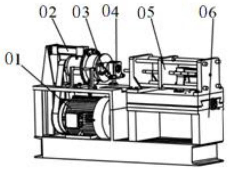
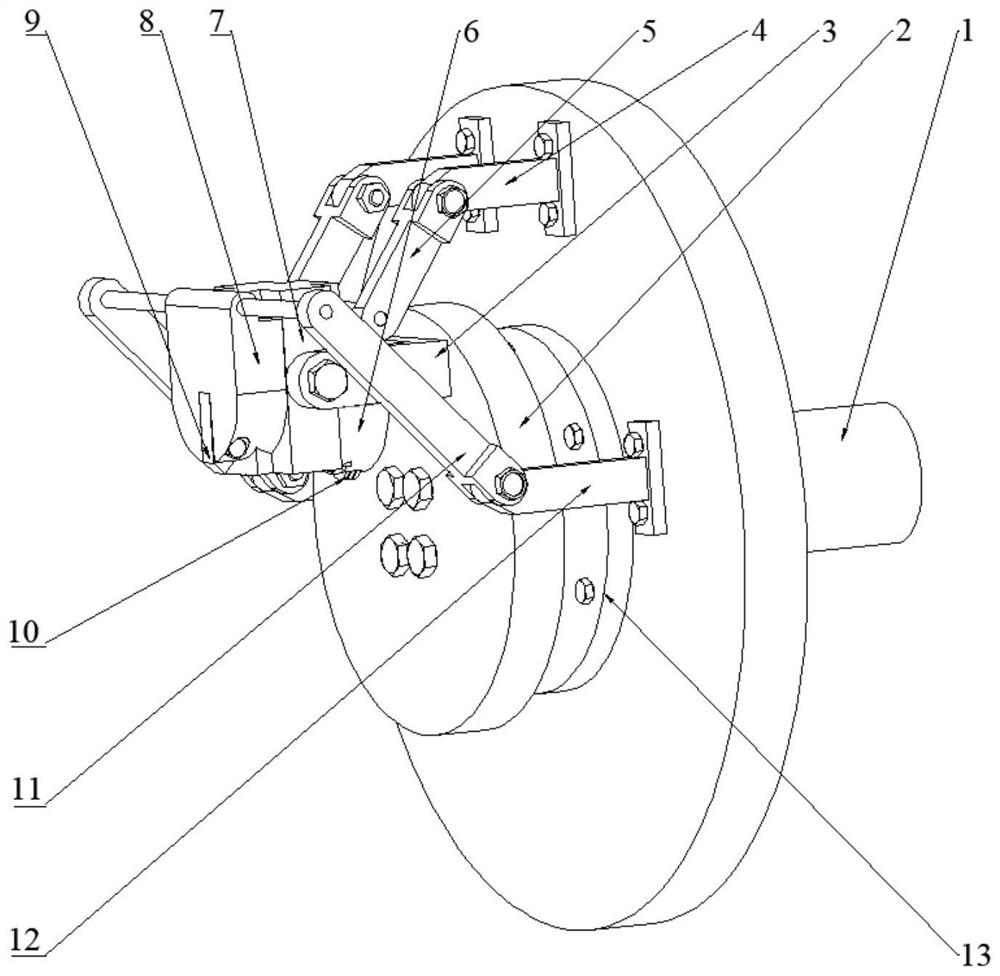
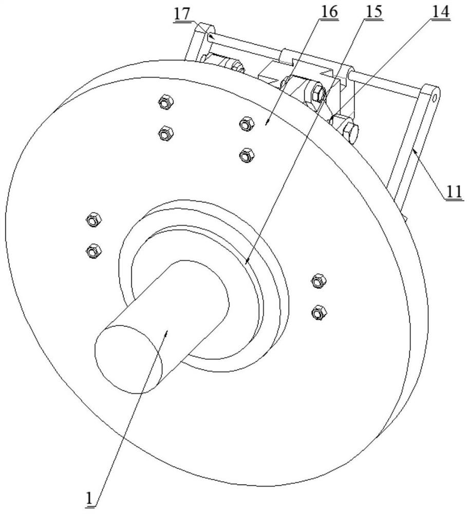
[0027] The following will combine Figure 1 to Figure 8 An integrated linkage device for slotting and cutting rods and pipes based on the same hydraulic compensation in the embodiment of the present invention will be described in detail.

[0028] An embodiment of the present invention provides an integrated linkage device for slotting and blanking of rods and pipes based on the same hydraulic compensation, which is used for low-stress b...


PUM


Abstract

The invention discloses an integrated linkage device for slotting and blanking of rods and pipes based on the same hydraulic compensation, which belongs to the technical field of machining. Different eccentric positions of different bending directions can be used to drive the blanking slider and the tool slider on both sides of the double dovetail slide table respectively, so that the reverse linkage of the blanking slider and the tool slider can be realized. , that is to say, through the reverse linkage mechanism, the slotting and unloading operations can be realized at the same time, and the slotting and unloading operations are "nearly synchronous", which greatly reduces the working hours, and the operation is simple and convenient. The roller structure of the groove, and then by adopting the new feeding method of continuous contact with the periphery of the roller hammer head, the limitation of the bearing size is solved, and the continuous contact feeding is realized, and the reclaiming operation is omitted, which saves the feeding time.

Description

technical field [0001] The invention relates to the technical field of machining, in particular to an integrated linkage device for slotting and unloading of rods and pipes based on the same hydraulic compensation. Background technique [0002] Low-stress blanking is to apply crack technology to bar (or pipe) blanking. First, a circumferential crack is artificially prefabricated on the surface of the bar (or pipe), and then the bar with the circumferential surface crack is (or pipe) apply a certain external force to make it dynamically separate in the form of low stress brittle fracture. Low-stress bending fracture blanking is recognized as the most promising precision blanking method in the future. It makes full use of the notch effect and bending effect of the circumferential V-shaped groove to achieve brittle fracture of materials at low stress levels and obtain geometry-free Distortion, vertical flat fracture, blank without chamfering. At present, scholars have conduct...

Claims


Application Information

Patent Timeline
Patent Type & Authority Patents(China)
IPC IPC(8): B23Q7/00B23Q5/22B26D3/06B26D7/18
CPCB23Q5/22B23Q7/00B26D3/06B26D7/18
Inventor 张立军杨宁金永山张德潇房绍伟徐嘉怡郭伟健
Owner CHINA UNIV OF PETROLEUM (EAST CHINA)
Learn More