Novel steel bar rust removal device

A steel bar, a new type of technology, used in grinding/polishing safety devices, grinding machines, metal processing equipment, etc., can solve the problems of slow construction progress, low rust removal efficiency, and large workload, so as to reduce physical expenditure and save removal. The effect of rust time and rust removal speed

Pending Publication Date: 2020-03-24
一山(北京)岩土工程有限公司
View PDF0 Cites 0 Cited by
  • Summary
  • Abstract
  • Description
  • Claims
  • Application Information

AI Technical Summary

Problems solved by technology

[0002] Steel bars are commonly used in the steel construction industry and other engineering industries. In the actual construction process, steel bars are usually stacked directly on the construction site. The surface of the steel bars is prone to rust after long-term exposure to wind and rain. The bond strength between them will be deteriorated, and the corrosion of steel bars will also be accelerated
[0003] Existing rust removal methods for steel bars include pickling, sand blasting and manual rust removal. Due to the high cost of pickling and sand blasting, manual rust removal is still commonly used on construction sites. For some short steel bars, construction workers use sandpaper to remove rust. Or steel balls are used to polish the surface of steel bars to achieve the purpose of rust removal. Obviously, this method has poor rust removal effect, low rust removal efficiency, and heavy workload, which slows down the construction progress and increases the labor burden of workers. to improve

Method used


Image

  • Novel steel bar rust removal device
  • Novel steel bar rust removal device
  • Novel steel bar rust removal device

Examples


Embodiment Construction

[0029] The present invention will be described in further detail below in conjunction with the accompanying drawings.

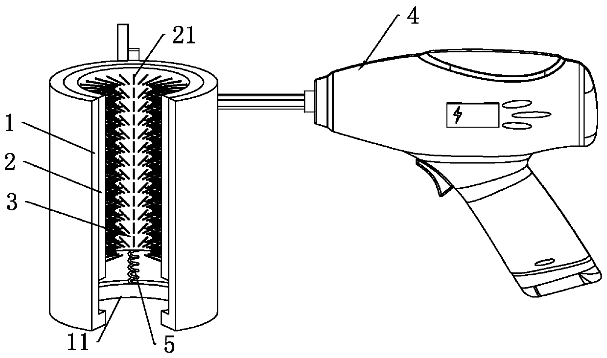
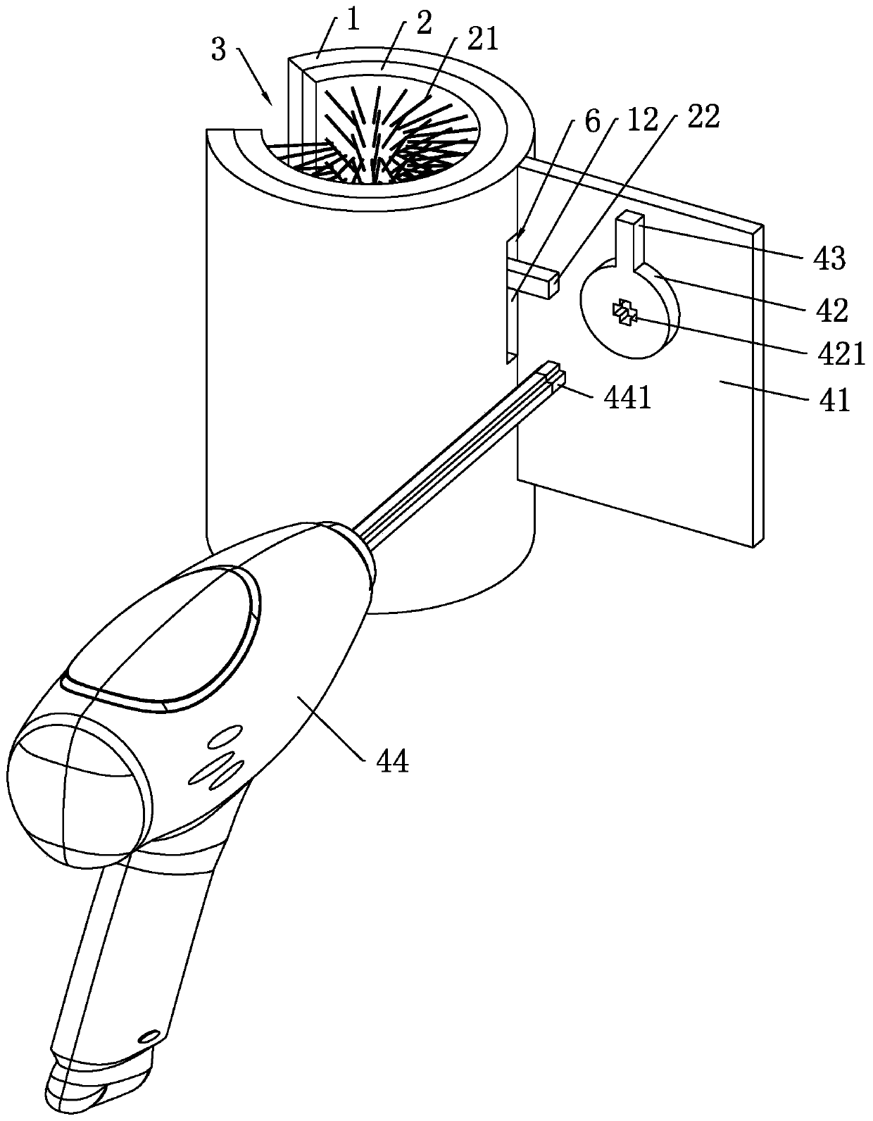
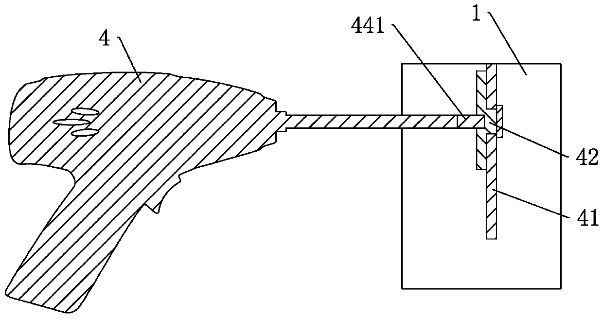
[0030] refer to figure 1 , is a new type of rust removal device for steel bars disclosed by the present invention, comprising a first casing 1 and a second casing 2, the first casing 1 is sleeved on the outside of the second casing 2, and the first casing 1 Longer than the second casing 2, the inner wall of the second casing 2 is evenly equipped with wire brushes 21, and the outer wall of the first casing 1 is fixedly equipped with a driving device 4. When in use, the rusty steel bar is extended into the second casing 2, drive the second casing 2 to slide up and down along the axial direction in the first casing 1 through the driving device 4, so that the wire brush 21 in the second casing 2 can clean the surface of the steel bar Repeated grinding to remove rust on the surface of the steel bar.

[0031] refer to figure 1 Specifically, the first casing 1 an...


PUM


Abstract

The invention relates to a novel steel bar rust removal device. The device is characterized by comprising a first protective cylinder and a second protective cylinder arranged in the first protectivecylinder in a sleeved mode, wherein steel wire brushes are uniformly distributed on an inner wall of the second protective cylinder, notches are vertically and downwards formed on the same sides of the first protective cylinder and the second protective cylinder, a cylinder bottom is formed at a bottom end of the first protective cylinder, a plurality of return springs are vertically arranged in the circumferential direction of the cylinder bottom, a top end of the reset spring is fixedly connected with a bottom end of a cylinder wall of the second protective cylinder, a guide hole is vertically formed in the middle section of the cylinder wall, deviating from the notch side, of the first protective cylinder, a guide block extending out of the guide hole is horizontally and fixedly connected with the cylinder wall, deviating from the notch side, of the second protective cylinder, and a driving device for repeatedly shifting the guide block to enable the guide block to vertically reciprocate in the guide hole is arranged outside the cylinder wall, close to one side of the guide block, of the first protective cylinder. The device is advantaged in that on the premise that the construction progress is guaranteed, rust on surfaces of steel bars can be evenly removed, the rust removing effect is good, efficiency is high, and the labor burden of workers is relieved.

Description

technical field [0001] The invention relates to the field of steel bar derusting, in particular to a novel steel bar derusting device. Background technique [0002] Steel bars are commonly used in the steel construction industry and other engineering industries. In the actual construction process, steel bars are usually stacked directly on the construction site. The surface of the steel bars is prone to rust after long-term exposure to wind and rain. The bond strength between them will be deteriorated, and the corrosion of steel bars will also be accelerated. [0003] Existing rust removal methods for steel bars include pickling, sand blasting and manual rust removal. Due to the high cost of pickling and sand blasting, manual rust removal is still commonly used on construction sites. For some short steel bars, construction workers use sandpaper to remove rust. Or steel balls are used to polish the surface of steel bars to achieve the purpose of rust removal. Obviously, this...

Claims


Application Information

Patent Timeline
Patent Type & Authority Applications(China)
IPC IPC(8): B24B27/033B24B27/00B24B23/02B24B55/00
CPCB24B23/02B24B27/0092B24B27/033B24B55/00
Inventor 兰玉金黄汉成李连森牟兰超魏宏源
Owner 一山(北京)岩土工程有限公司
Why Eureka
Try Eureka