Electric bridge driving system and vehicle

A drive system and electric bridge technology, applied in the field of vehicles, can solve the problems of large transmission ratio, complex structure, low cost of electric bridge drive system, etc., and achieve the effect of reducing costs and improving transmission efficiency

Pending Publication Date: 2020-03-24
SCHAEFFLER TECH AG & CO KG
View PDF2 Cites 1 Cited by
  • Summary
  • Abstract
  • Description
  • Claims
  • Application Information

AI Technical Summary

Problems solved by technology

[0003] In the layout concept of a parallel structure with spur gear sets, the cost of the bridge drive system is low, but it is difficult to achieve a large transmission ratio in a compact construction space
Patent US2017175863A1 discloses a parallel layout scheme of an electric bridge drive system, in which an intermediate shaft and multiple spur gear sets are provided, however, a large transmission ratio can only be obtained when the gear diameter is large, so in a compact structure Larger transmission ratios c

Method used


Image

  • Electric bridge driving system and vehicle
  • Electric bridge driving system and vehicle

Examples


Embodiment Construction

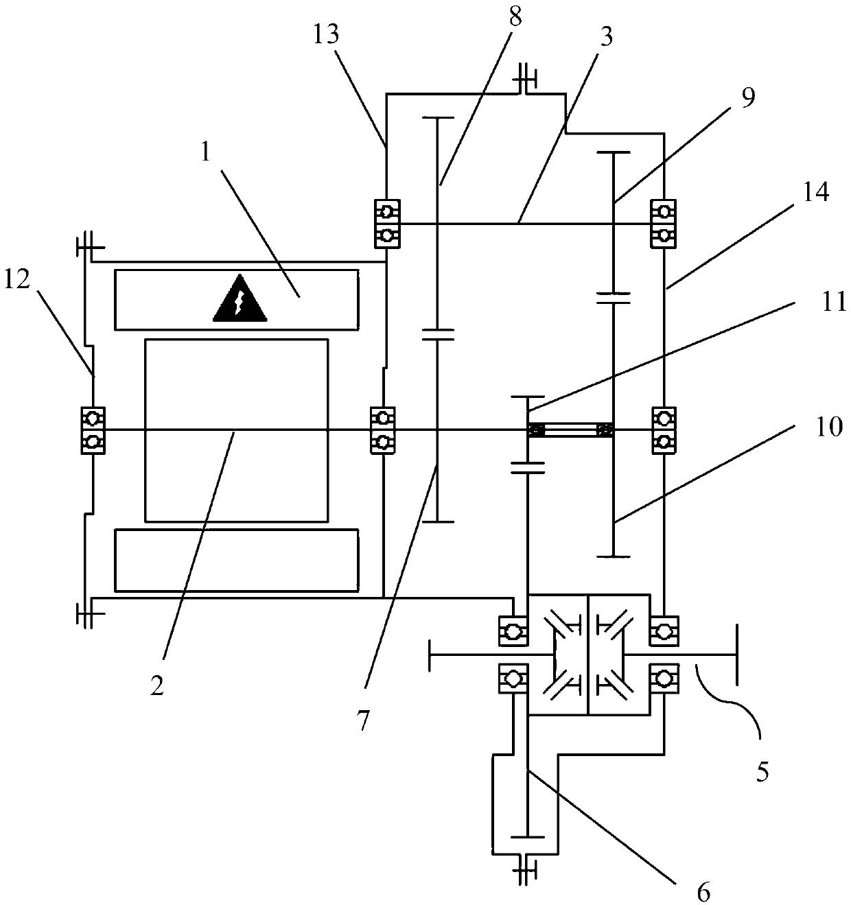
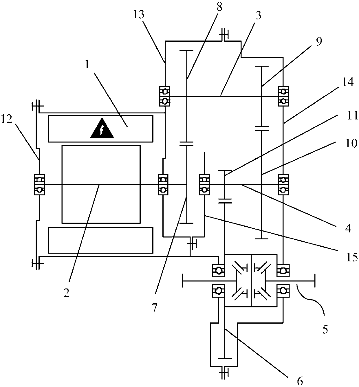
[0020] figure 1 A schematic structural diagram of the bridge drive system according to the first preferred embodiment of the present invention is shown. The bridge drive system is a single-speed drive system for pure electric vehicles or hybrid vehicles. The bridge drive system includes a motor 1 , a transmission, a differential 5 and a system housing surrounding the bridge drive system. The transmission can transmit the power of the motor 1 to the differential 5, and then distribute it to the wheels of the vehicle to drive the vehicle.

[0021] As shown in the figure, the motor 1 is, for example, an inner rotor motor, and has a motor shaft 2 arranged on the same rotation axis as the motor shaft 2, which is connected to the rotor. The differential 5 is an ordinary gear differential, and has a driven gear 6 . The two half shafts of the differential 5 are arranged offset from the motor shaft of the electric machine. The transmission has a motor shaft 2 , an intermediate shaf...


PUM


Abstract

The invention relates to an electric bridge driving system and a vehicle. The electric bridge driving system comprises a motor (1), a speed changer, a differential mechanism (5) and a system shell surrounding the electric bridge driving system. The transmission can transmit power of the motor to the differential mechanism (5). The transmission is provided with a motor shaft (2) connected with themotor. The differential mechanism (5) is provided with a driven gear (6) serving as a power input end; wherein the transmission further comprises an intermediate shaft (3) parallel to the motor shaft(2), a first gear (7) is arranged on the motor shaft in an anti-torque manner; a second gear (8) and a third gear (9) are arranged on the intermediate shaft in an anti-torque manner; a fourth gear (10) and a fifth gear (11) which are connected to each other in a rotationally fixed manner are also provided in the transmission, the first gear and the second gear meshing with each other, the third gear and the fourth gear meshing with each other, and the fifth gear and the driven gear meshing with each other, the electric machine and the differential being arranged biased, and the vehicle has thebridge drive system according to the invention.

Description

technical field [0001] The invention relates to the technical field of vehicles. In particular, the invention relates to an electric bridge drive system for pure electric vehicles or hybrid vehicles. The invention also relates to a vehicle comprising the aforementioned bridge drive system. Background technique [0002] The bridge drive system is used in hybrid vehicles or pure electric vehicles, especially in small vehicles. The electric axle drive system integrates the electric motor, the fixed-ratio transmission and the differential, and connects the two driven wheels by two half shafts. In the prior art, the bridge drive system has different layout schemes, such as a parallel structure using spur gears, a coaxial structure using a planetary gear mechanism, and a parallel structure using spur gears and planetary gears. [0003] In the case of a parallel configuration with spur gear sets, the cost of the bridge drive is low, but it is difficult to achieve a large transmi...

Claims


Application Information

Patent Timeline
IPC IPC(8): B60K1/00B60K17/16B60K17/12
CPCB60K1/00B60K17/12B60K17/16
Inventor 刘磊钟虎
Owner SCHAEFFLER TECH AG & CO KG
Why Eureka
Try Eureka