Check patentability & draft patents in minutes with Patsnap Eureka AI!

Thermal protection system for aircraft

A technology for aircraft and heat protection, applied in the direction of fuselage insulation, etc., can solve the problems of affecting the aerodynamic parameters of the aircraft, and the rectification block increasing the weight of the aircraft, so as to improve the anti-ablation performance, good heat resistance and reliability, and improve the heat resistance performance effect

Active Publication Date: 2020-03-24
THE GENERAL DESIGNING INST OF HUBEI SPACE TECH ACAD
View PDF12 Cites 5 Cited by
  • Summary
  • Abstract
  • Description
  • Claims
  • Application Information

AI Technical Summary

Problems solved by technology

However, the increase of the rectifying block will first increase the weight of the aircraft itself, and secondly, because the rectifying block has a certain volume, it will affect the aerodynamic parameters of the aircraft under high-speed flight to a certain extent

Method used


Image

  • Thermal protection system for aircraft

Examples


Embodiment Construction

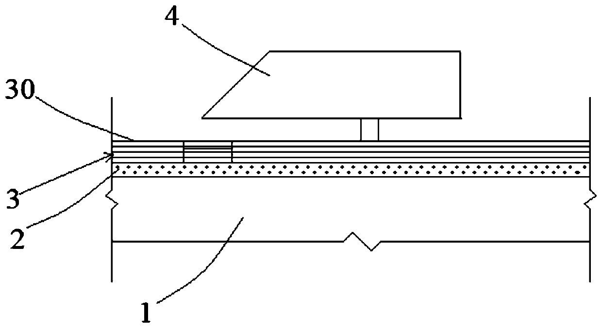
[0020] Embodiments of the present invention will be described in further detail below in conjunction with the accompanying drawings.

[0021] see figure 1 As shown, the embodiment of the present invention provides a thermal protection system for an aircraft, including an aircraft body 1, the outer wall of the aircraft body 1 is laid with a heat insulation layer 2 and a heat protection layer 3 from the inside to the outside, and the heat protection layer 3 is far away from the heat insulation layer 2 is provided with an air rudder 4 on one side, and the heat-proof layer 3 includes a first heat-proof zone and a second heat-proof zone. The second heat-proof zone is located below the rudder tip of the air rudder 4. Both are the first heat protection zone, and the first heat protection zone and the second heat protection zone are laid with multiple layers of prepreg 30 , and the laying density of the second heat protection zone is greater than that of the first heat protection zone...


PUM

PropertyMeasurementUnit
Thicknessaaaaaaaaaa
Sizeaaaaaaaaaa

Abstract

The invention discloses a thermal protection system of an aircraft, and relates to the technical field of thermal protection of aircrafts. The thermal protection system includes an aircraft body, a heat insulation layer and a heat prevention layer are laid on the outer wall of the shell from inside to outside. An air rudder is arranged on one side, far away from the heat insulation layer, of the heat prevention layer; the heat prevention layer comprises a first heat prevention area and a second heat prevention area; wherein the second heat prevention area is located below a rudder tip of the air rudder, the remaining areas of the heat prevention layer are the first heat prevention area, multiple layers of prepreg cloth are laid on the first heat prevention area and the second heat prevention area, and the laying density of the second heat prevention area is larger than that of the first heat prevention area. According to the thermal protection system of the aircraft, the local ablationresistance is improved by improving the laying density of the second heat prevention area, and the problem that aerodynamic parameters and the appearance of the aircraft are affected due to the factthat a rectification block is additionally arranged in the second heat prevention area is avoided.

Description

technical field [0001] The invention relates to the technical field of aircraft thermal protection, in particular to an aircraft thermal protection system. Background technique [0002] In order to adapt to the harsh aerodynamic and thermal environment of aerospace vehicles with long endurance and high Mach number, the thermal protection design of aerospace vehicles is becoming more and more important. It is becoming more and more complex, especially the heat-resistant layer near the tip of the air rudder of the aircraft needs special consideration in the performance of heat protection. There will be a large shock wave interference at the tip, and the aerodynamic thermal environment of the aircraft heat shield here will be worse than that of other parts of the heat shield, so it is necessary to improve the anti-ablation performance of the heat shield here The requirements of the aircraft will be much higher than other parts of the aircraft, so as to ensure that the aircraft...

Claims


Application Information

Patent Timeline
IPC IPC(8): B64C1/40
CPCB64C1/40
Inventor 范开春杨攀胡善刚王辉陈兴峰
Owner THE GENERAL DESIGNING INST OF HUBEI SPACE TECH ACAD
Features
  • R&D
  • Intellectual Property
  • Life Sciences
  • Materials
  • Tech Scout
  • Unparalleled Data Quality
  • Higher Quality Content
  • 60% Fewer Hallucinations
Learn More