Eureka AIR delivers breakthrough ideas for toughest innovation challenges, trusted by R&D personnel around the world.

Rear ventilation cooling device of piston engine

A piston engine, ventilation and cooling technology, applied in the cooling system of the power plant, motor vehicles, transportation and packaging, etc., can solve the problems of complex and irregular engine shape, loose connectors and pipelines, and hidden dangers of flight safety, and achieve cylinder The body cooling response speed is fast, the aerodynamic resistance is small, and the cooling efficiency is high

Pending Publication Date: 2020-03-24
XIAN AISHENG TECH GRP +1
View PDF7 Cites 10 Cited by
  • Summary
  • Abstract
  • Description
  • Claims
  • Application Information

AI Technical Summary

Problems solved by technology

[0003] Some existing UAVs use the method of exposing the engine for ventilation and cooling. Because the shape of the engine is complex and irregular, with many protrusions, direct exposure to the airflow will generate greater aerodynamic resistance, and it is also easy to make the exposed connectors on the engine And the pipeline is loose, resulting in flight safety hazards
The ventilation and cooling system of most other drones consists of a fairing, an air inlet, an air deflector, and an exhaust port. The air deflector is arranged inside the fairing to guide the cooling airflow, and the air inlet is mostly fixed. , protruding from the surface of the fuselage, but the aerodynamic resistance is relatively large

Method used


Image

  • Rear ventilation cooling device of piston engine
  • Rear ventilation cooling device of piston engine
  • Rear ventilation cooling device of piston engine

Examples


Embodiment Construction

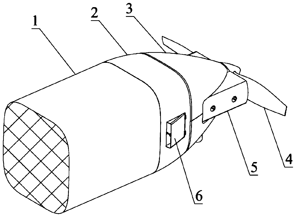
[0022] This embodiment is a rear ventilation cooling device for a piston engine.

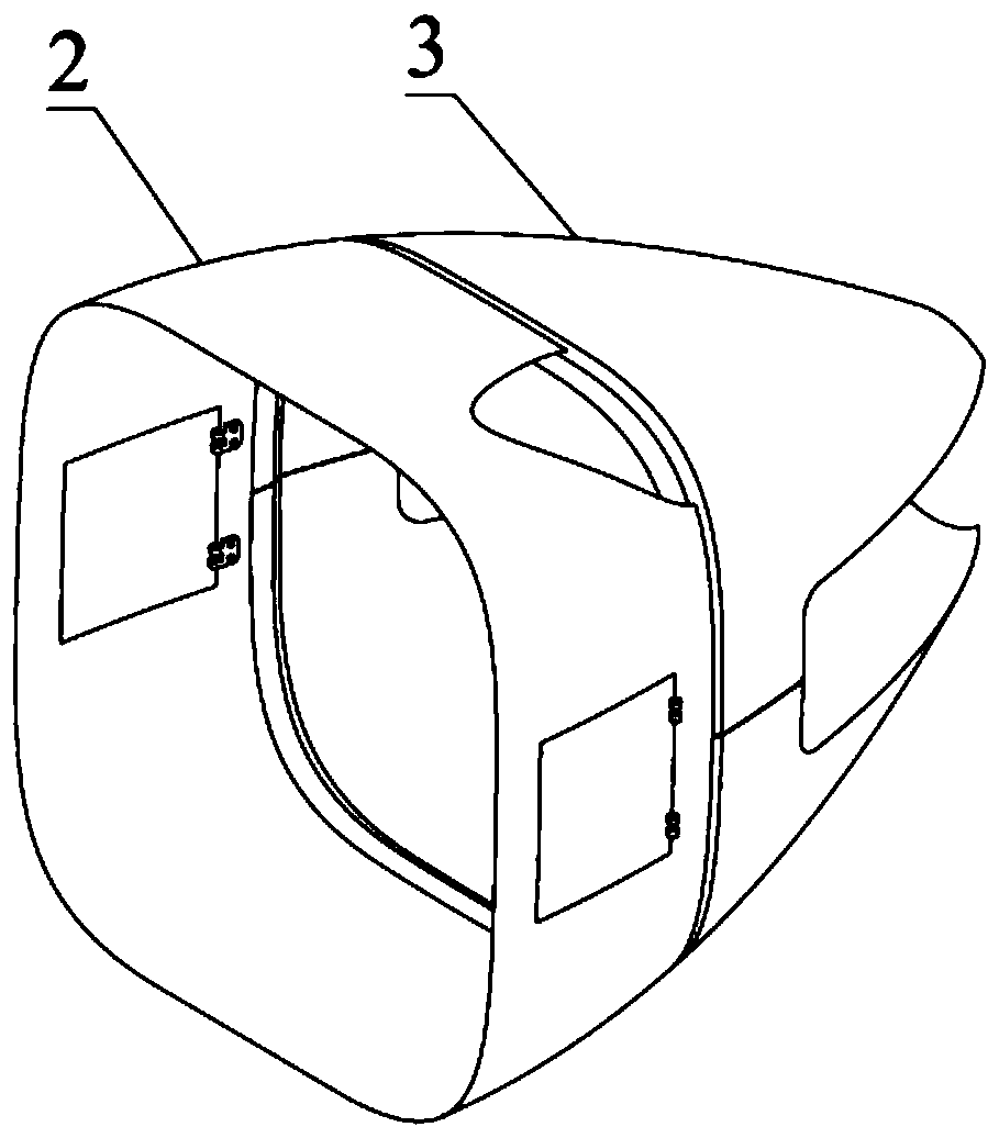
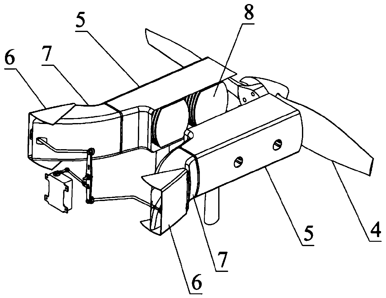
[0023] refer to Figure 1 ~ Figure 4 , The present embodiment piston engine rear ventilation cooling device is made up of fuselage 1, propeller 4, shroud 5, airway door 6, airway 7, engine block 8, fairing and operating mechanism. In this example, the engine is a four-cylinder horizontally opposed type, and the engine and cooling system are installed at the tail of the fuselage 1; among them, the fairing is used to rectify the engine with irregular shape, and the fairing is divided into the front part 2 of the fairing and the rear part of the fairing 3. The front part 2 of the fairing is installed on the surrounding structure of the engine frame at the tail of the fuselage 1, and the rear part 3 of the fairing is installed on the engine. External incoming flow enters the interior of the fairing. A safety gap is reserved between the front section 2 of the fairing and the rear section 3 of the f...


PUM


Abstract

The invention discloses a rear ventilation cooling device of a piston engine, and relates to the technical field of unmanned aerial vehicle piston engines, an engine fairing and a fuselage are coordinated in appearance for aerodynamic design, an air channel door is completely attached to the fairing after being closed, the opening degree is controllable after the air channel door is opened, cooling airflow is introduced into an air channel from an external flow field, and closed-loop control over an engine cylinder body is achieved through adjustment of the air inflow. According to the flightspeed of the unmanned aerial vehicle, the environment temperature and the engine cylinder temperature, the air passage door is controlled to be opened at different opening degrees, the engine cylindertemperature is controlled within the optimal temperature range, the engine cooling air entraining requirement is met, and the flight resistance can be reduced. Forced convection heat dissipation is conducted on the engine cylinder body in the flow guide cover, cooling airflow flows out of a rear opening of the flow guide cover, the section of the rear opening of the flow guide cover is close to the rotating plane of the propeller, auxiliary heat dissipation can be conducted through the suction effect of the propeller during work, the cylinder body cooling response speed is high, the structureis simple, and the cooling efficiency is high.

Description

technical field [0001] The invention relates to the technical field of unmanned aerial vehicle piston engines, in particular to a rear ventilation cooling device for piston engines. Background technique [0002] Piston engines are widely used in small and medium-sized unmanned aerial vehicles. In the layout design, the rear installation of the engine is the most common. For example, UAVs such as the Israeli Heron, the American Predator, and my country’s Rainbow series all adopt the rear installation layout of the piston engine. . Piston engines are divided into air-cooled and liquid-cooled. Most light-duty piston engines are air-cooled. When installing air-cooled piston engines, a ventilation cooling system needs to be designed. [0003] Some existing drones use the method of exposing the engine for ventilation and cooling. Because the shape of the engine is complex and irregular, and there are many protrusions, direct exposure to the airflow will generate greater aerodynami...

Claims


Application Information

Patent Timeline
IPC IPC(8): B64D33/08
CPCB64D33/08B64U50/11
Inventor 王力安国锋介苏朋展全伟
Owner XIAN AISHENG TECH GRP
Why Eureka
Eureka Blog
Learn More