Pressure sensor based on surface enhanced Raman scattering

A surface-enhanced Raman and pressure sensor technology, applied in the field of sensors, can solve the problems of large size, inability to provide electrical output, heavy mass, etc., and achieve high accuracy and sensitivity

Inactive Publication Date: 2020-03-24
西安柯莱特信息科技有限公司
View PDF0 Cites 0 Cited by
  • Summary
  • Abstract
  • Description
  • Claims
  • Application Information

AI Technical Summary

Problems solved by technology

Traditional pressure sensors are mainly mechanical structural devices, and the deformation of elastic elements is use

Method used


Image

  • Pressure sensor based on surface enhanced Raman scattering
  • Pressure sensor based on surface enhanced Raman scattering
  • Pressure sensor based on surface enhanced Raman scattering

Examples


Embodiment 1

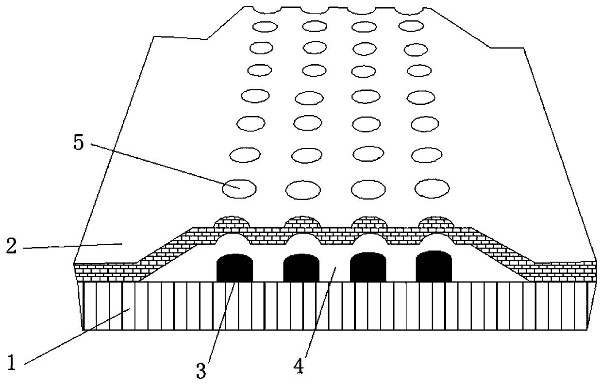
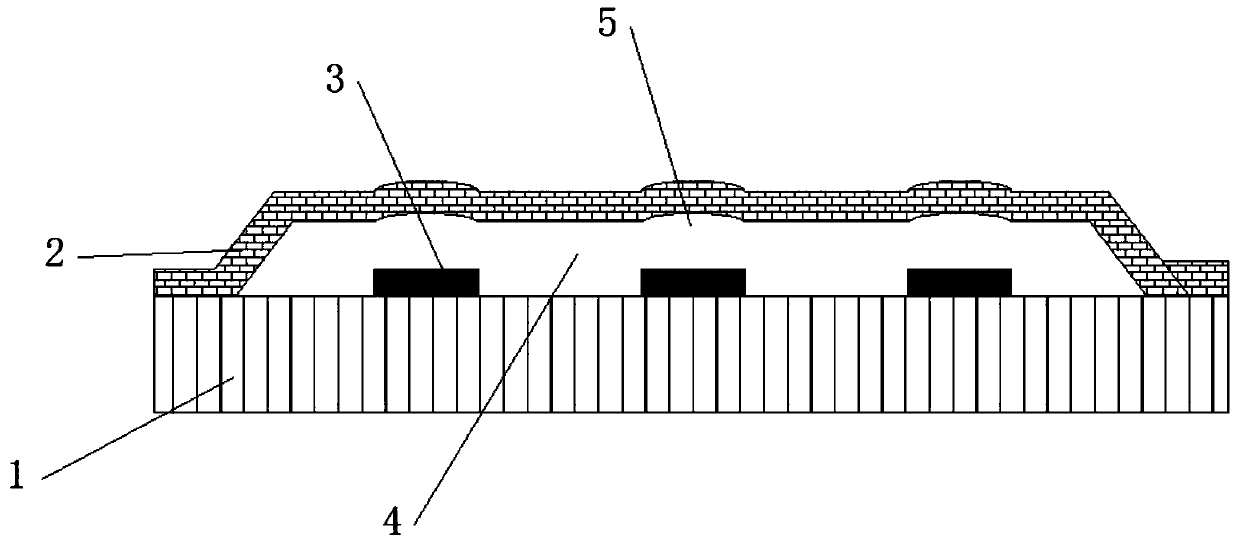
[0024] This embodiment provides a figure 1 The shown pressure sensor based on surface-enhanced Raman scattering includes a base layer 1, which mainly plays a supporting role and can transmit light. Therefore, the base layer 1 can be made of silicon dioxide; the base layer 1 A metal layer 2 is arranged above the base layer 1, and a cavity 4 is formed between the metal layer 2 and the base layer 1, specifically, as figure 2 , image 3 As shown, the cross section of the metal layer 2 is trapezoidal, the left and right sides are in contact with the base layer 1, and the middle part is not in contact with the base layer 1, so that a cavity 4 is formed between the metal layer 2 and the base layer 1; The metal layer 2 is also provided with periodically arranged holes 5, specifically, the holes 5 are located in the middle part of the metal layer 2, and the top of the base layer 1 is located at the vertical projection of the holes 5. The micro-nano metal particle layer 3 that is per...

Embodiment 2

[0031] This embodiment provides a image 3 The shown pressure sensor based on surface-enhanced Raman scattering includes a base layer 1, which mainly plays a supporting role and can transmit light. Therefore, the base layer 1 can be made of silicon dioxide; the base layer 1 A metal layer 2 is arranged above the base layer 1, and a cavity 4 is formed between the metal layer 2 and the base layer 1, specifically, as image 3 As shown, the cross section of the metal layer 2 is trapezoidal, the left and right sides are in contact with the base layer 1, and the middle part is not in contact with the base layer 1, so that a cavity 4 is formed between the metal layer 2 and the base layer 1; The metal layer 2 is also provided with periodically arranged holes 5, specifically, the holes 5 are located in the middle part of the metal layer 2, and the top of the base layer 1 is located at the vertical projection of the holes 5. The micro-nano metal particle layer 3 in a permanent arrangeme...

Embodiment 3

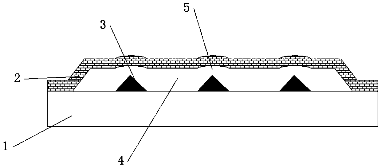
[0038] On the basis of Example 1, such as Figure 4 As shown, the hole 5 is a triangular hole; the shape of the micro-nano metal particle layer 3 projected vertically in the hole 5 is a triangular column, which is conducive to the accumulation of large charges in the hole 5 and the micro-nano metal particle layer 3. On the tip of the triangle, the localized intensity of the electric field is greater, and the measurement accuracy is higher.


PUM

PropertyMeasurementUnit
Diameteraaaaaaaaaa
Heightaaaaaaaaaa
Thicknessaaaaaaaaaa

Abstract

The invention relates to a pressure sensor based on surface enhanced Raman scattering. The sensor comprises a substrate layer. A metal layer is arranged above the substrate layer, a cavity is formed between the metal layer and the substrate layer, holes arranged periodically are further formed in the metal layer, and micro-nano metal particle layers arranged periodically are arranged at the positions, located at the vertical projection positions of the holes, above the substrate layer. According to the pressure sensor based on surface enhanced Raman scattering, a pressure signal can be converted into an optical signal, and the pressure is detected by detecting the change of Raman scattering of the optical signal. When pressure is applied to the sensor, pressure extrudes the metal layer, and changes the height of the cavity, so an electromagnetic field generated by incident light between the metal layer and the micro-nano metal particle layer is changed. The intensity of a Raman spectrum characteristic peak is further changed. Pressure detection can be achieved by detecting the change of the Raman spectrum characteristic peak, and higher accuracy and sensitivity are achieved.

Description

technical field [0001] The invention belongs to the technical field of sensors, in particular to a pressure sensor based on surface-enhanced Raman scattering. Background technique [0002] A sensor (English name: transducer / sensor) is a detection device that can feel the measured information, and can transform the sensed information into an electrical signal or other required form of information output according to a certain rule, so as to meet the information requirements. transmission, processing, storage, display, recording and control requirements. [0003] The characteristics of sensors include: miniaturization, digitization, intelligence, multi-function, systemization, and networking. It is the first link to realize automatic detection and automatic control. The existence and development of sensors allow objects to have senses such as touch, taste, and smell, and make objects come alive slowly. Usually according to its basic perception function, it can be divided in...

Claims


Application Information

Patent Timeline
IPC IPC(8): G01L1/24G01L11/02
CPCG01L1/24G01L11/02
Inventor 不公告发明人
Owner 西安柯莱特信息科技有限公司
Why Eureka
Try Eureka