Device for directly controlling a blade by means of an electromechanical actuator

A blade, direct technology, applied in the field of aircraft, can solve the problems of not providing enough electromechanical interaction, system instability, etc., to achieve the effect of high compactness, simple operation and high responsiveness

Active Publication Date: 2020-03-24
亚恩雷蒙德阿尔伯特威林格
View PDF7 Cites 1 Cited by
  • Summary
  • Abstract
  • Description
  • Claims
  • Application Information

AI Technical Summary

Problems solved by technology

Some direct blade control systems provide one or more coils to control the cyclic pitch of the blades, but the proposed systems are unstable or do not provide sufficient electromechanical interaction to provide direct blade control

Method used


Image

  • Device for directly controlling a blade by means of an electromechanical actuator
  • Device for directly controlling a blade by means of an electromechanical actuator
  • Device for directly controlling a blade by means of an electromechanical actuator

Examples


Embodiment Construction

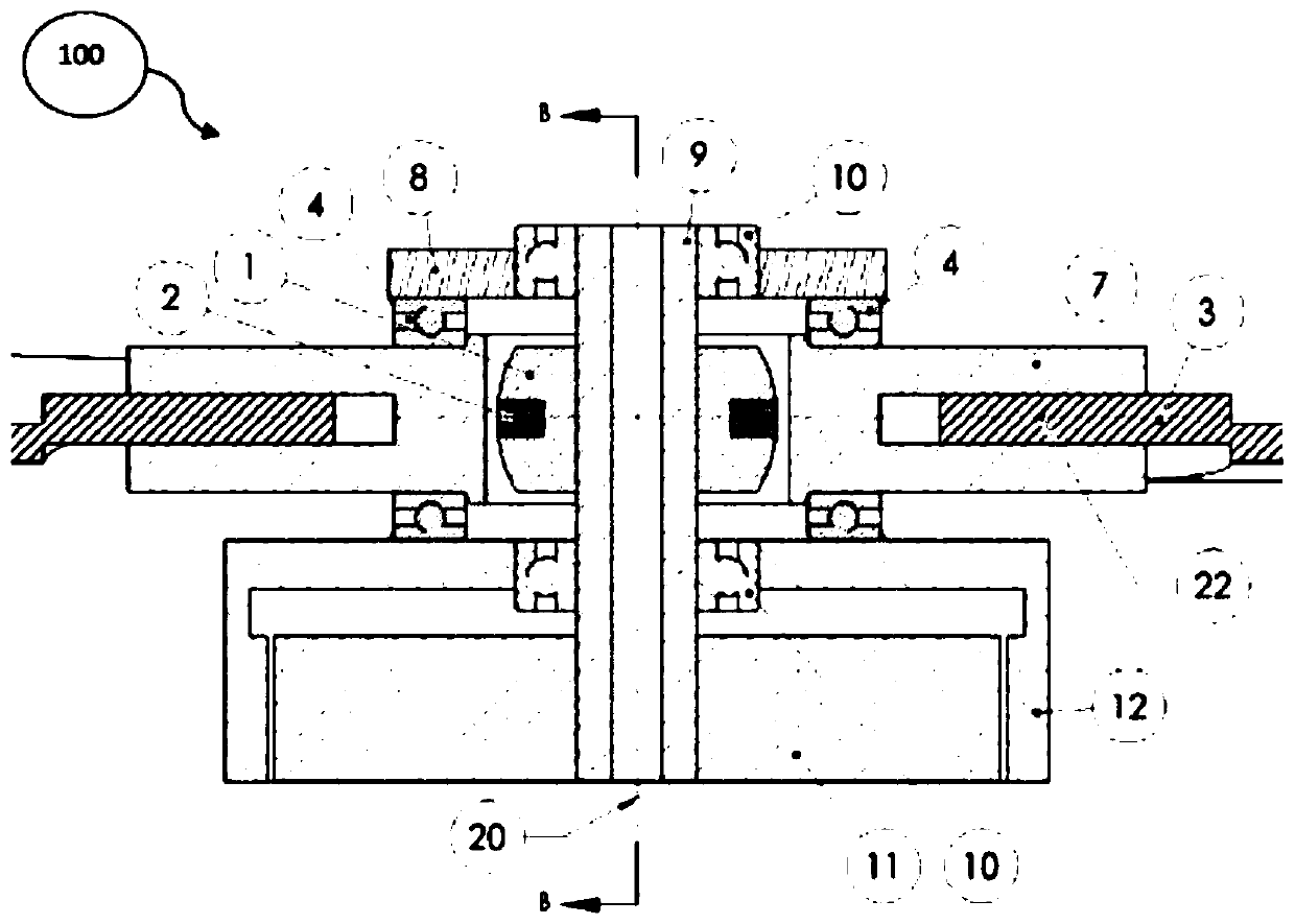
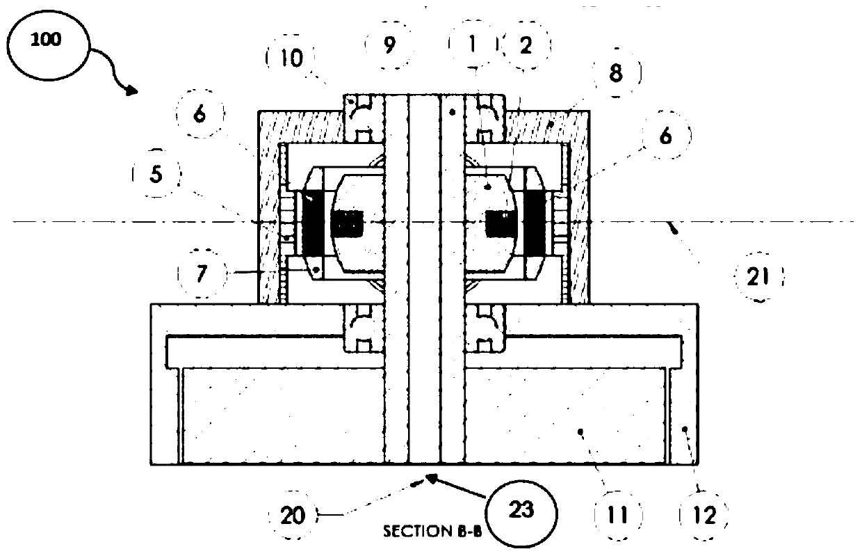
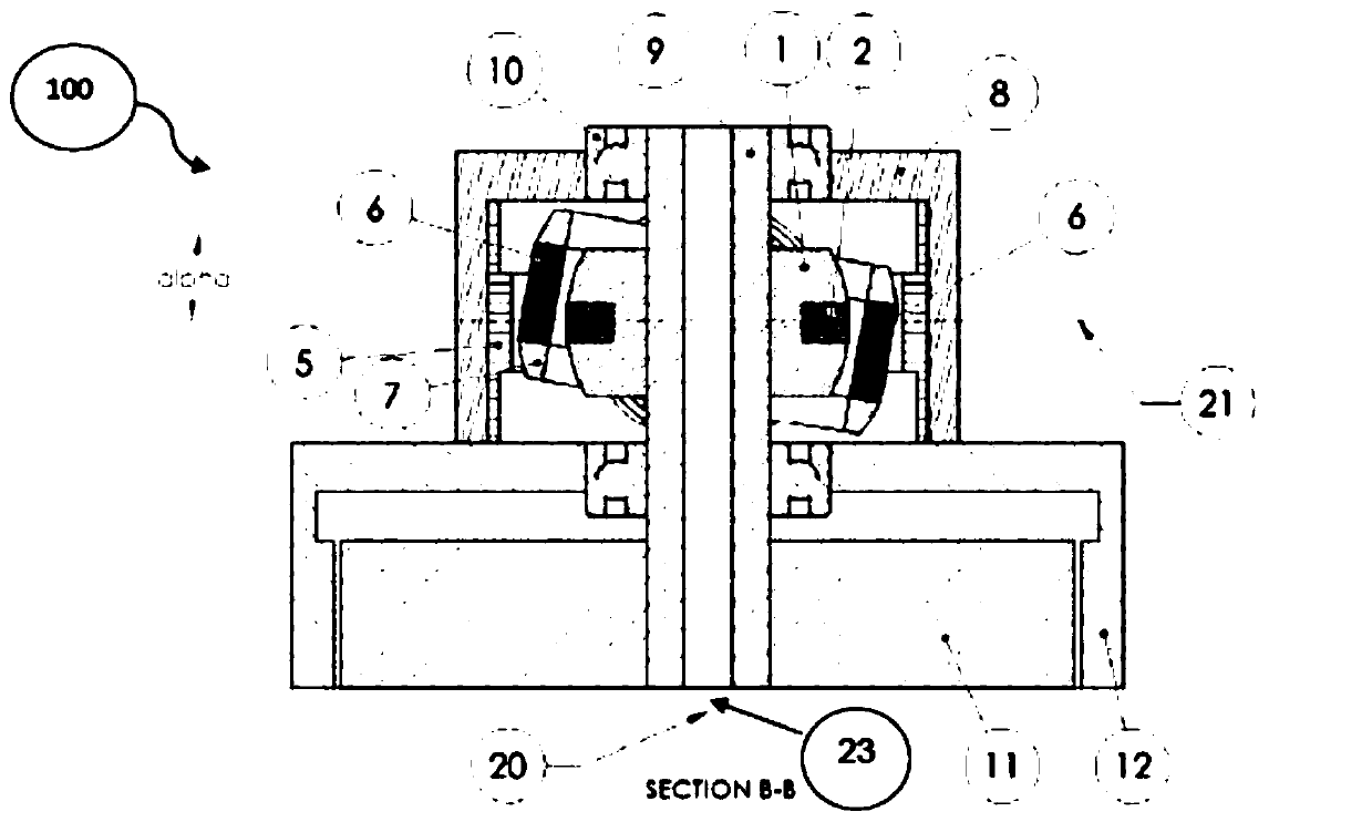
[0043] The blade carrier (7) and the blade (3) are pivotally connected to the rotor (8) by bearings (4), the angular rotation of which is limited by + or -α angle corresponding to the blade relative to its neutral paddle angle of change. In the case of cyclic pitch maneuvering with two blades fixed together ( figure 1 , 2 , 3, 4), when one blade increases from the angle α, the opposite blade decreases by the same angle, so that the cyclic pitch control can be performed.

[0044] The stator (1) is ferromagnetic spherical and consists of coils (2). According to the direction of the current, in one direction of the current, the upper part is the north pole and the lower part is the south pole. vice versa.

[0045] according to figure 1 , 2 , 3 and 4, the blade carrier (7) consists of two magnets (6) of opposite poles, namely a north pole and a south pole, so that when the stator (1) is energized, one of the magnets attracts the other for the upper part of the stator (1) mag...


PUM


Abstract

The present invention relates to a device for directly controlling a blade which comprises a stator (1), at least one blade support (7) composed of at least one curved magnet (6), the blade support (7) being secured to at least one blade (3) and pivotally coupled to the rotor (8) for varying the alpha angle of said blades with the excitation of the stator (1). The stator (1) is a partially spherical stator, the stator core (1) being the intersection of the blade axis (22) and the rotor axis (20), said stator being radially close to the magnets (3) to control the rotation of the blades (3) around the blade axis (22). A magnetic ring (5) holds the blades (3) in a neutral position, the system can be compared to a cyclically controlled mechanical oscillator, the frequency, phase and amplitudeof the oscillation being controlled by said stator. The invention relates to a device providing a compact, lightweight and robust solution for controlling the direction of an aircraft.

Description

technical field [0001] The present invention relates to a direct blade manipulation device and an aircraft with the system, more specifically but not exclusively to a main rotor of a small aircraft, especially a small UAV vertical take-off and landing aircraft. Background technique [0002] In the prior art, the cyclic and collective pitch steering of the helicopter rotor blades is performed by means of a swashplate driven by an actuator. Assemblies of linkages and mechanical parts are actuated to cyclically manipulate the blades to generate the torque that allows the aircraft to orient itself. [0003] Such a system requires at least two actuators that orient the non-rotating part of the swashplate, the rotating part through the links controls the blade angle according to its position according to a sinusoidal function. [0004] The complexity of these mechanical systems, and their weight limit their use on some aircraft, especially small ones, mainly because at least two ...

Claims


Application Information

Patent Timeline
Patent Type & Authority Applications(China)
IPC IPC(8): B64C27/12B64C27/72B64C11/44B63H3/00B64C39/00
CPCB64C2203/00B64C11/44B64C27/12B64C27/72B64C39/024Y02T50/30B64U10/10
Inventor 亚恩·雷蒙德·阿尔伯特·威林格
Owner 亚恩雷蒙德阿尔伯特威林格
Why Eureka
Try Eureka