Natural gas filtration and dehydration equipment

A technology for filtration and dehydration and natural gas, which is applied in the fields of gas fuel, petroleum industry, fuel, etc., can solve the problems of low efficiency, numerous equipment and high cost, and achieve the effect of convenient viewing.

Pending Publication Date: 2020-03-27
长沙星沙新奥燃气有限公司
View PDF0 Cites 5 Cited by
  • Summary
  • Abstract
  • Description
  • Claims
  • Application Information

AI Technical Summary

Problems solved by technology

At present, cooling natural gas is usually used for dehydration, that is, the natural gas is introduced from the bottom of the dehydration tower, and then the cold air is introduced from the top of the dehydration tower, and then the cold air is convectively con...

Method used


Image

  • Natural gas filtration and dehydration equipment
  • Natural gas filtration and dehydration equipment
  • Natural gas filtration and dehydration equipment

Examples


Embodiment 1

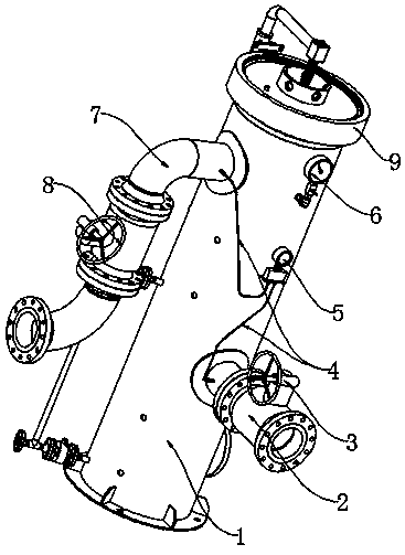
[0052] see Figure 1-7 , a kind of natural gas filter dehydration equipment of the present invention, comprises:

[0053] Tank body 1, the tank body 1 is a long cylindrical structure;

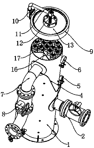
[0054] Demister 21, said demister 21 is arranged on the bottom of said tank body 1, wherein,

[0055] The top of the demister 21 is connected with the lower support plate 20;

[0056] Folded plate 16, the folded plate 16 is arranged on the top of the demister 21, wherein, the top of the folded plate 16 is welded to the upper support plate 19, wherein,

[0057] A cavity 18 is formed between the flap 16 and the tank body 1;

[0058] Cyclone separator 17, the cyclone separator 17 is arranged on the top of the upper support plate 19;

[0059] An air intake duct 7, one end of the air intake duct 7 communicates with the cavity 18 inside the tank body 1;

[0060] An exhaust pipe 2, one end of the exhaust pipe 2 communicates with the bottom of the tank body 1;

[0061] A cover assembly, the cover a...

Embodiment 2

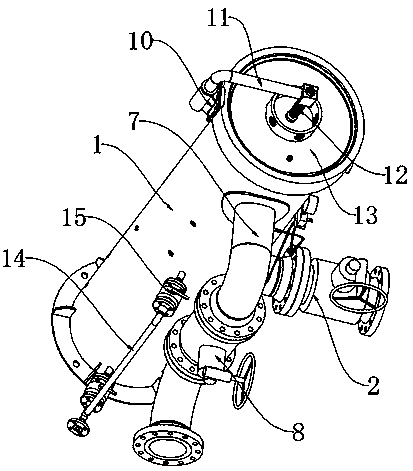
[0064] see Figure 1-7 , the present invention is a kind of natural gas filtration and dehydration equipment, and the cover assembly includes:

[0065] A cover 9, the cover 9 is set on the top of the tank 1;

[0066] A fixing base 10, the fixing base 10 is fixed on one side of the cover 9;

[0067] A rotating shaft 11, one end of the rotating shaft 11 is inserted into the inside of the fixed seat 10, so that the rotating shaft 11 can rotate inside the fixed seat 10;

[0068] Screw mandrel 12, one end of described screw mandrel 12 is fixed with the other end of described rotating shaft 11;

[0069] A sealing cover 13, the sealing cover 13 is arranged inside the cover body 9, wherein,

[0070] The outer edge of the sealing cover 13 is threadedly connected with the inner edge of the cover body 9 , so as to realize the threaded connection between the middle part of the sealing cover 13 and the screw rod 12 .

[0071] When the sealing cover 13 needs to be opened, the sealing co...


PUM


Abstract

The invention belongs to the technical field of natural gas filtration and dehydration, and discloses natural gas filtration and dehydration equipment. The top of a folded plate is welded with an upper supporting plate, and a cavity is formed between the folded plate and a tank body. A cyclone separator is arranged at the upper part of the upper supporting plate; one end of an air inlet pipeline is communicated with the cavity in the tank body; one end of an exhaust pipeline is communicated with the bottom of the tank body; and a cover body assembly covers the top of the tank body. The cycloneseparator and the demister are arranged, natural gas entrained with liquid and solid particles enters the cavity formed by the tank body and the folded plate through the gas inlet pipeline and then the entrained liquid and solid particles are filtered through the cyclone separator and the demister, the gas is exhausted from the exhaust pipeline after filtering, the gas component analyzer arrangedin the exhaust pipeline can detect the filtered gas, the detection information is displayed on the upper part of the display screen and the operator can check the detection information conveniently.

Description

technical field [0001] The invention relates to the technical field of natural gas filtration and dehydration, in particular to natural gas filtration and dehydration equipment. Background technique [0002] Generally speaking, during the process of drilling natural gas, the natural gas flowing out of the well is usually saturated with gas-phase water, and even carries a certain amount of liquid water. During the use of natural gas, the presence of moisture in natural gas often causes serious consequences, such as moisture blocking valves, pipes and equipment of natural gas pipelines. For this reason, natural gas manufacturers need to dehydrate natural gas. [0003] The dehydration work of natural gas is usually realized by natural gas dehydration unit. The dehydration methods used in natural gas dehydration units include low temperature method, solvent absorption method, solid adsorption method, chemical reaction method and membrane separation method. At present, cooling...

Claims


Application Information

Patent Timeline
IPC IPC(8): C10L3/10
CPCC10L3/101C10L3/106
Inventor 李斌秦波王龙彭俊勇陈艳萍刘华强
Owner 长沙星沙新奥燃气有限公司
Why Eureka
Try Eureka