Combined bearing
A combined bearing and bearing technology, which is applied in the field of bearings, can solve the problems of high lubricant dependence and large friction, and achieve the effects of low cost, low friction and low dependence
- Summary
- Abstract
- Description
- Claims
- Application Information
AI Technical Summary
Problems solved by technology
Method used
Image

Examples
Embodiment 1
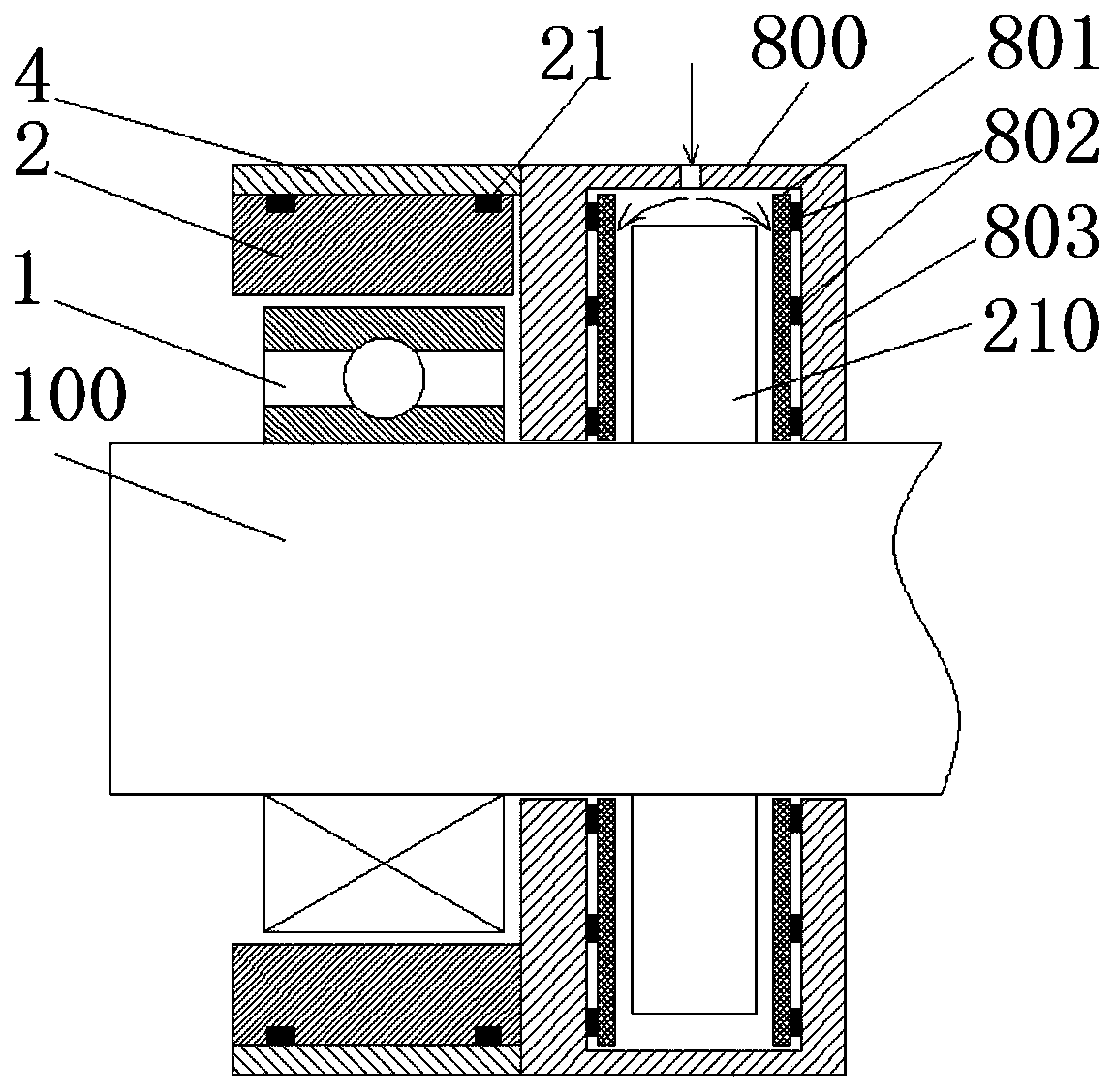
[0050] The rotating shaft bearing 1 is a ball bearing, and the stator bearing 2 is an air bearing.
[0051] see figure 1, the parallel bearing in this embodiment includes a shaft bearing 1 and a stator bearing 2 . The rotating shaft bearing 1 is sleeved on the rotating shaft 100 , and the stator bearing 2 is sleeved outside the rotating shaft bearing 1 and maintains a certain gap with the outer wall of the rotating shaft bearing 1 .
[0052] The air bearing is in the shape of an annular cylinder, the outer wall of which is parallel to the end surface and at least one annular groove is provided, and a damper is nested in the annular groove, and the damper is an annular rubber ring 21, and the top of the rubber ring 21 protrudes from the Air bearing outer wall.
[0053] see Image 6 , 7 , 8, 9, on the annular end surface of the air bearing, a plurality of bumps 22 are evenly distributed around the axial direction, and one end of the air bearing with the bumps 22 is provided ...
Embodiment 2
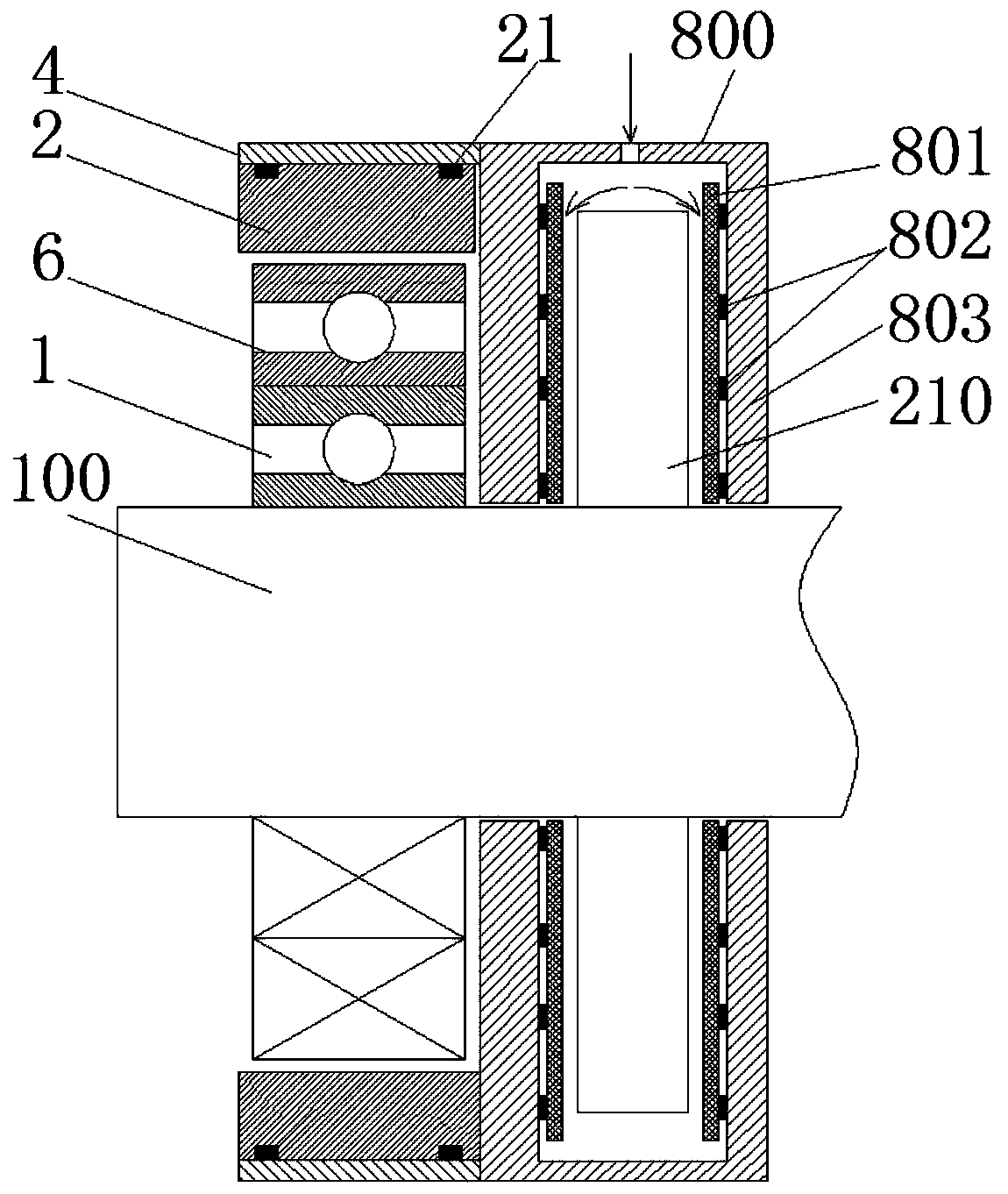
[0056] see figure 2 , the parallel bearing also includes at least one intermediate bearing 6, the intermediate bearing 6 is a contact bearing, the intermediate bearing 6 is sleeved between the rotating shaft bearing 1 and the stator bearing 2, and the stator bearing 2 and the intermediate bearing 6 There are gaps in between.
[0057] The intermediate bearing 6 is a ball bearing.
[0058] Specifically, the parallel bearing includes a shaft bearing 1 , a stator bearing 2 and an intermediate bearing 6 .
[0059] In this embodiment, on the basis of the first embodiment, an intermediate bearing 6 is sleeved on the rotating shaft bearing 1 (or a plurality of intermediate bearings 6 are sheathed sequentially and each intermediate bearing 6 is coaxial), and the stator bearing 2 is sleeved on the outermost Outside the intermediate bearing 6, and keep a certain gap with the outer wall of the outermost intermediate bearing 6.
Embodiment 3
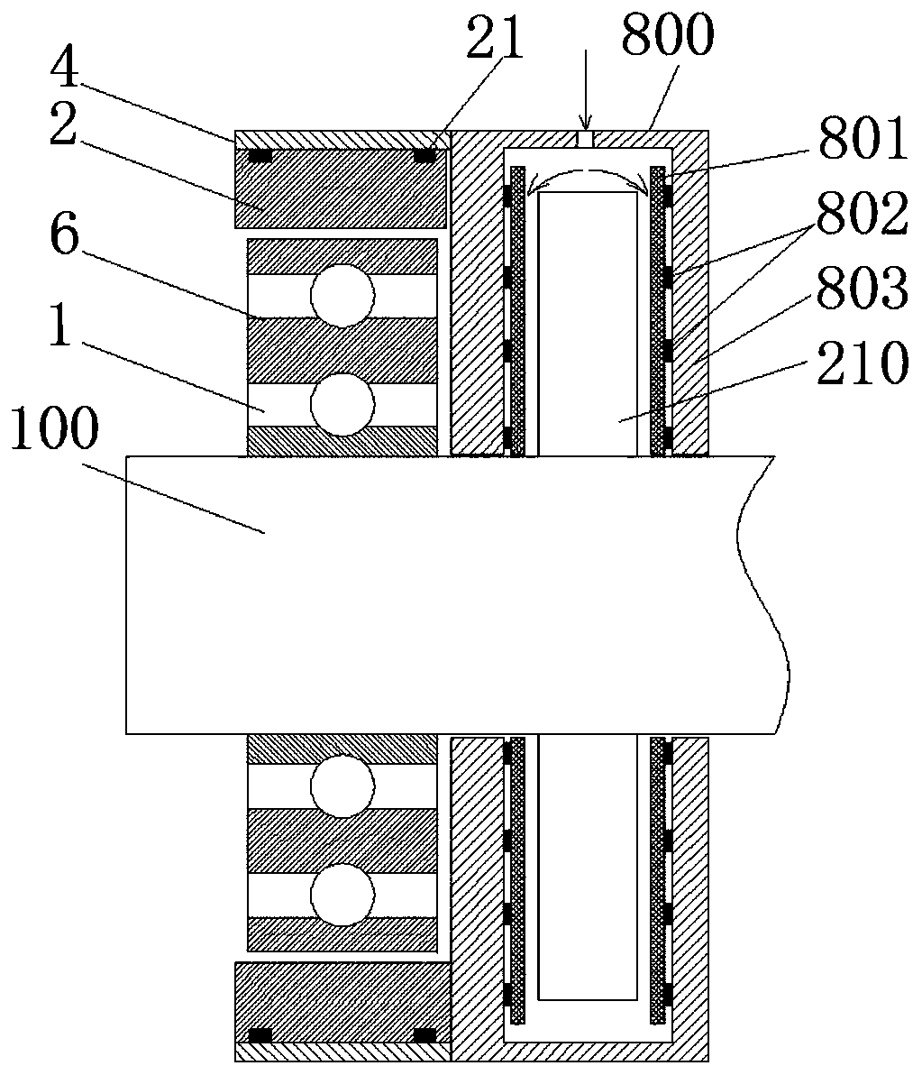
[0061] Further, the ball bearing, roller bearing, ceramic bearing or tetrafluoroethylene bearing is single-layer, double-layer or multi-layer. The ball bearing or roller bearing of the rotating shaft bearing 1 in Embodiment 1 and Embodiment 2 of the present invention can be an integrated multi-layer bearing, and the ball layer or roller layer is arranged in multiple layers, see image 3 . Multilayer ball bearings or roller bearings include inner rings, intermediate rings and outer rings that are nested with each other, and balls or rollers are respectively embedded between the inner rings and intermediate rings, and between the intermediate rings and outer rings.
PUM
 Abstract
Description
Claims
Application Information
 - Generate Ideas
- Intellectual Property
- Life Sciences
- Materials
- Tech Scout
- Unparalleled Data Quality
- Higher Quality Content
- 60% Fewer Hallucinations
Browse by: Latest US Patents, China's latest patents, Technical Efficacy Thesaurus, Application Domain, Technology Topic, Popular Technical Reports.
© 2025 PatSnap. All rights reserved.Legal|Privacy policy|Modern Slavery Act Transparency Statement|Sitemap|About US| Contact US: help@patsnap.com