
Ultralow-temperature high-bearing bidirectional sealing device

A two-way sealing, high load-bearing technology, applied in the direction of engine sealing, engine components, mechanical equipment, etc., can solve the problems of short life of the shaft hole sealing structure, short life of the sealing structure, poor processing technology, etc., and achieve low cost and simple assembly , long service life effect

Active Publication Date: 2020-03-27
XIAN AEROSPACE PROPULSION INST
View PDF6 Cites 0 Cited by
  • Summary
  • Abstract
  • Description
  • Claims
  • Application Information

AI Technical Summary

Problems solved by technology

[0004] The purpose of the present invention is to solve the problems of short service life, high cost, large structural size, poor workmanship and poor sealing performance in the existing shaft hole sealing structure, and to provide a two-way sealing device with ultra-low temperature and high load
The ultra-low temperature and high load-bearing two-way sealing device of the present invention adopts a dynamic and static sealing separation scheme to solve the above-mentioned problems of short life of the sealing structure, poor sealing performance, large structural size and poor processing technology, and provides an effective solution for the dynamic sealing of the ultra-low temperature system.

Method used


Image

  • Ultralow-temperature high-bearing bidirectional sealing device
  • Ultralow-temperature high-bearing bidirectional sealing device
  • Ultralow-temperature high-bearing bidirectional sealing device

Examples


Embodiment Construction

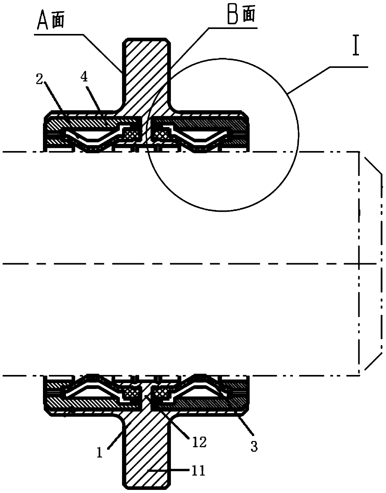
[0018] In order to improve the pressure adaptability of the existing shaft hole sealing structure and improve its ultra-low temperature characteristics, the present invention provides an ultra-low temperature and high-load bidirectional sealing device. The partial structure of the moving shaft hole seal can be used, which can improve the sealing performance of the existing common ultra-low temperature structures that require shaft hole sealing, and can work in a larger pressure range and can also be used at lower temperatures.

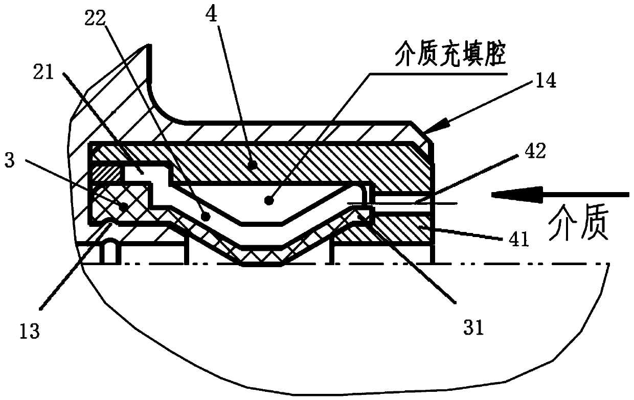
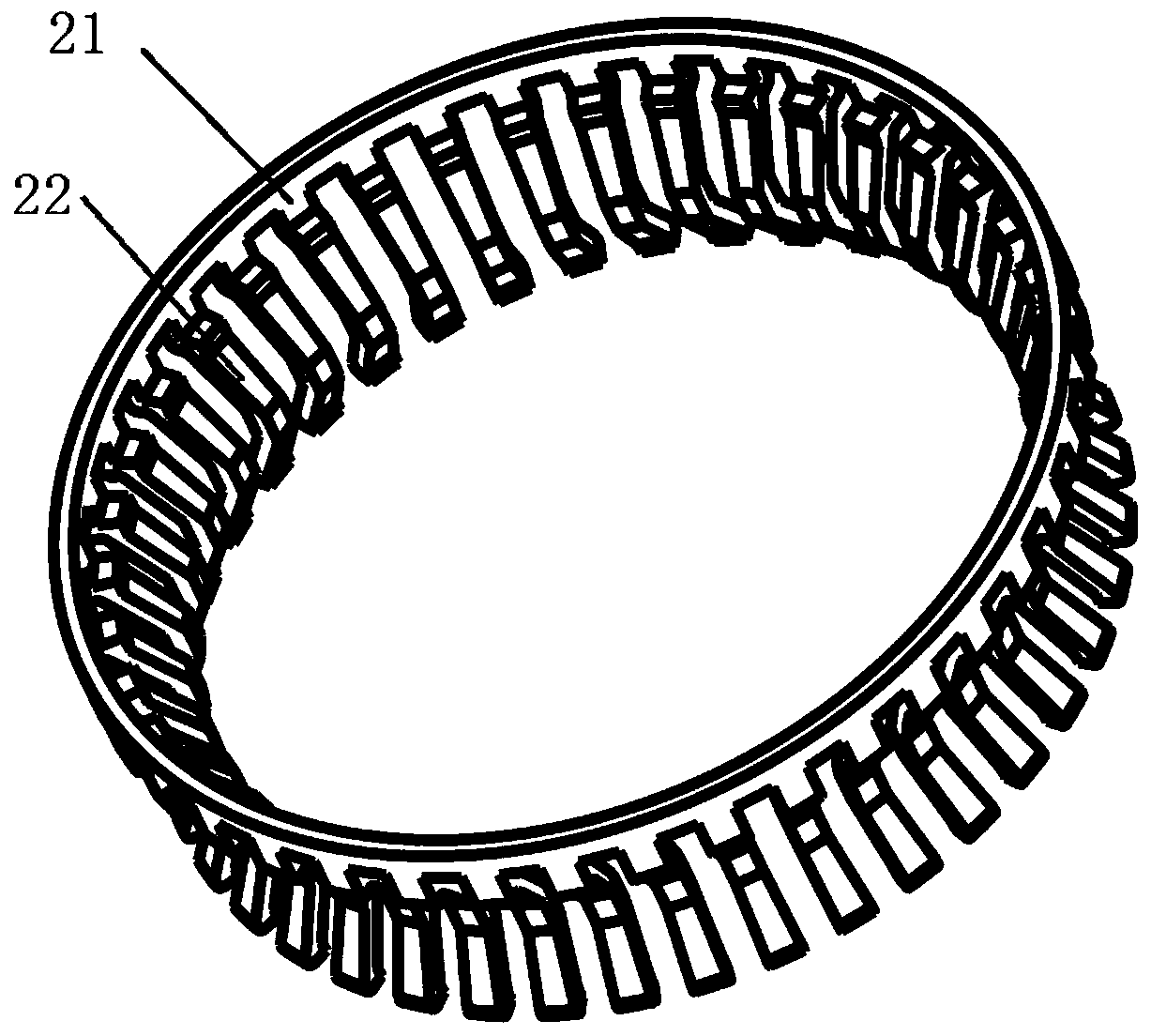
[0019] like Figure 1 to Figure 3 As shown, the ultra-low temperature and high load-bearing bidirectional sealing device provided by the present invention includes a sealing frame 1 and two sets of dynamic sealing units. The dynamic sealing unit includes a spring sheet 2, a plastic ring 3 and a pressing sleeve 4; the sealing frame 1 is a sleeve structure, an annular sealing plate 11 is provided on the outer end surface of the sleeve, and the two end su...


PUM


Abstract

The invention relates to an ultralow-temperature high-bearing bidirectional sealing device. The device solves the problems of short service life, high cost and poor sealing performance of an existingshaft hole sealing structure. The device comprises a sealing framework and two dynamic sealing units; each dynamic sealing unit comprises a spring leaf, a plastic ring and a pressing sleeve; the sealing framework is of a sleeve structure, an annular sealing plate is arranged on the outer end surface of the sleeve structure, the two end surfaces of the annular sealing plate are in contact with a sealed device to form static sealing surfaces, a partition plate is arranged on the inner surface of the sleeve structure and divides a sleeve inner cavity symmetrically into two sealing cavities, the sealing units are in the sealing cavities correspondingly, the pressing sleeves are arranged in the sealing cavities, annular bosses are arranged on the inner surfaces of the tail ends of the pressingsleeves, and axial pressure guide holes are formed in the annular bosses; the front end of each plastic ring is arranged on the partition plate of the sealing framework, the middle part of the plasticring is pressed on a mounting shaft, and the tail end of the plastic ring is arranged on the annular boss of the corresponding pressing sleeve; and the spring leaves are arranged between the plasticrings and the pressing sleeves in a sleeve mode, and each spring leaf comprises a fixing ring and multiple elastic membrances.

Description

technical field [0001] The invention relates to a sealing device, in particular to an ultra-low temperature and high load-bearing bidirectional sealing device. Background technique [0002] In liquefied natural gas, ultra-low temperature liquid rocket engines and test systems, the shaft hole sealing structure has a wide range of uses. Existing commonly used ultra-low temperature (minimum to -196 ℃) shaft hole sealing structures include flooding dynamic seals, packing seals and metal thin-wall seals. Among them, the pan-plug dynamic seal has a short life at ultra-low temperature, and the metal thin-walled sealing structure has high requirements for production and processing. The structural processing is difficult, the cost is high, and the production cycle is long; the service life of the packing seal is short, and the sealing performance is deteriorated due to the lack of compensation structure after repeated actions. [0003] There are a large number of low-temperature dy...

Claims


Application Information

Patent Timeline
Patent Type & Authority Applications(China)
IPC IPC(8): F16J15/46F16J15/16
CPCF16J15/16F16J15/46
Inventor 胡攀李小龙刘铭董万峰赵双龙
Owner XIAN AEROSPACE PROPULSION INST
Learn More