Straw stirring and drying device

A drying device and straw technology, applied in drying, drying machine, drying gas arrangement and other directions, can solve the problems of overloading of stirring equipment, low feed intake and digestibility, and insufficient texture, and achieve synchronous operation. , reduce the failure rate, the effect of good mixing effect

Inactive Publication Date: 2020-03-27
程成
View PDF8 Cites 5 Cited by
  • Summary
  • Abstract
  • Description
  • Claims
  • Application Information

AI Technical Summary

Problems solved by technology

[0002] After the straw is crushed, it can be made into feed or pressed into shape, but the water content of different varieties of straw is not uniform, the crushed straw is easy to agglomerate, the texture is not soft enough, and the feed intake and digestibility are low, so it is necessary to dry it deal with
The current straw mixing equipment mostly adopts a single mixing method, which is not effectively combined with the drying equipment. After the mixing is completed, it is sent to the drying production line for drying treatment, which requires multiple equipment, and also involves the transfer of straw materials. Cost High efficiency, low efficiency; moreover, the straw material on the drying production line is mostly continuous, and the inside of the straw stockpile is not easy to dry, so repeated drying is required; in addition, the existing straw mixing equipment uses continuous feeding , it is easy to lead to the overload operation of the mixing equipment, and even the phenomenon of jamming, resulting in damage to the equipment and a high failure rate

Method used


Image

  • Straw stirring and drying device
  • Straw stirring and drying device
  • Straw stirring and drying device

Examples


Embodiment Construction

[0024] In order to make the technical means, creative features, goals and effects achieved by the present invention easy to understand, the present invention will be further described below in conjunction with specific embodiments.

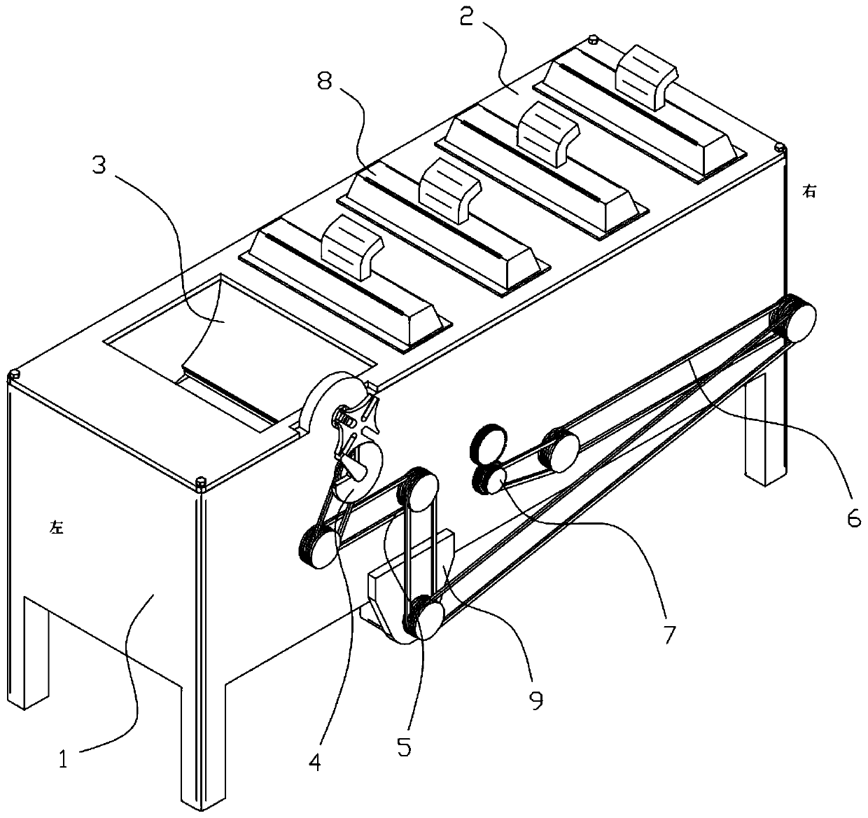
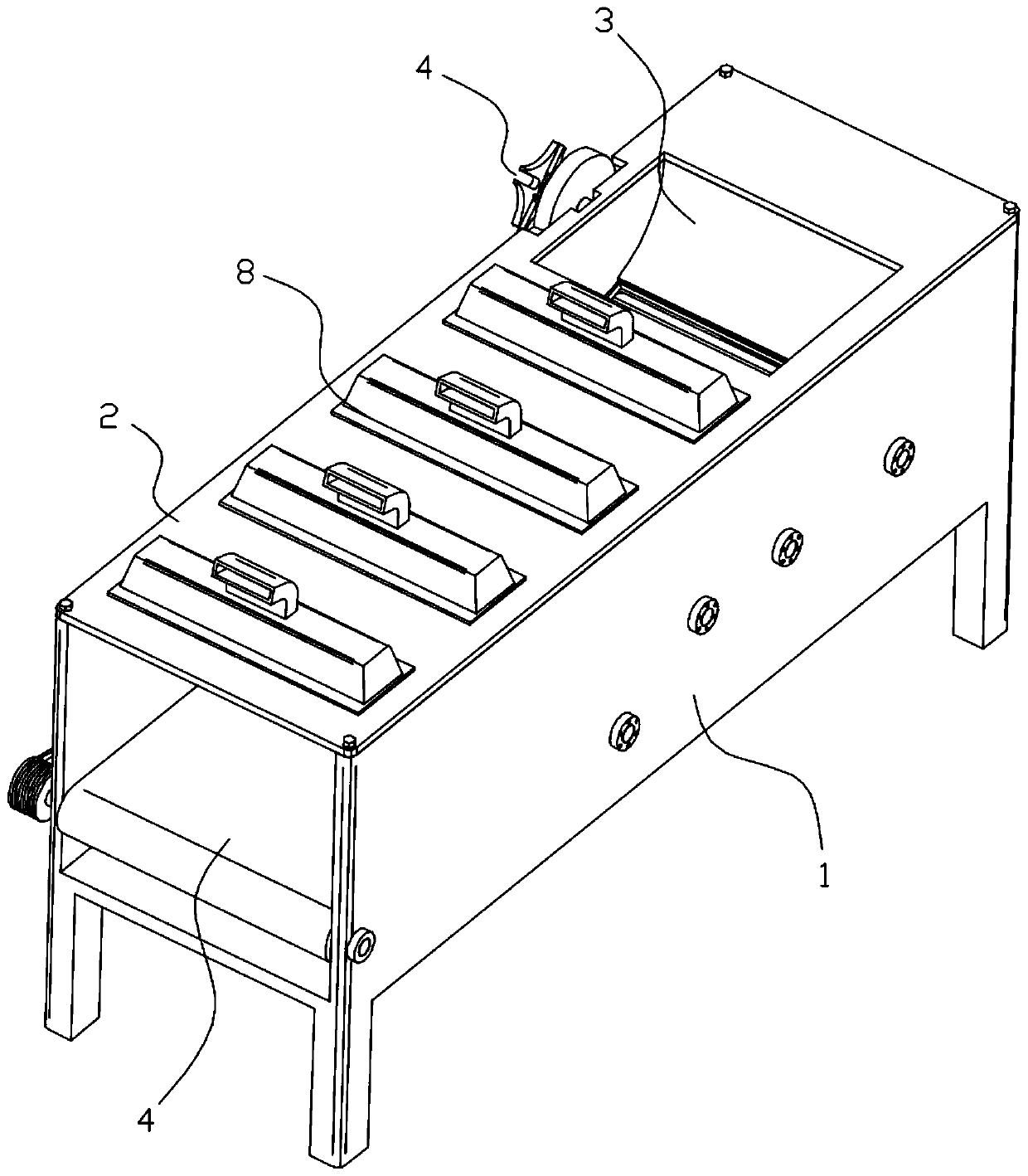
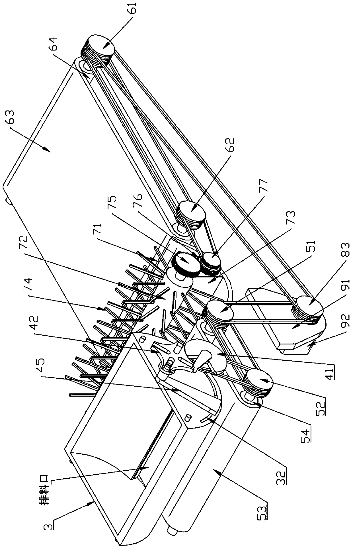
[0025] Such as Figure 1 to Figure 8 As shown, a straw mixing drying device includes a box body 1, a feeding hopper 3, an intermittent opening and closing mechanism 4, a primary conveyor belt mechanism 5, a mixing mechanism 7, a secondary conveyor belt mechanism 6, a driving mechanism 9 and Drying assembly 8, the box body 1 is a shell structure with openings on the upper end and the right end, the box cover 2 is installed on the top of the box body 1, and the feeding hopper 3 is installed on the left end of the box body 1 and is located at the first level Above the conveyor belt mechanism 5, the mixing mechanism 7 and the secondary conveyor belt mechanism 6 are sequentially arranged on the right side of the primary conveyor belt mechanism 5, and t...


PUM


Abstract

The invention discloses a straw stirring and drying device, and relates to the technical field of environmental protection. The straw stirring drying device comprises a box, a feeding hopper, an intermittent opening and closing mechanism, a primary conveyor belt mechanism, a stirring mechanism, a secondary conveyor belt mechanism, a driving mechanism and a drying assembly. The intermittent openingand closing mechanism capable of achieving intermittent opening and closing is arranged at the position of the feeding hopper, intermittent discharging at the position of the feeding hopper can be achieved, traditional continuous discharging is changed, and straw on the primary conveyor belt mechanism is conveyed section by section. Particularly, hot-blast air can enter a straw stack from the side face of the straw, and the straw can be dried. Meanwhile, due to the fact that straw entering the stirring mechanism is intermittent every time, the straw can be matched with the follow-up stirringmechanism to achieve the good mixing effect. In addition, due to the fact that no overloaded condition exists, the fault rate of equipment is lowered.

Description

technical field [0001] The invention belongs to the technical field of environmental protection, and in particular relates to a straw mixing drying device. Background technique [0002] After the straw is crushed, it can be made into feed or pressed into shape, but the water content of different varieties of straw is not uniform, the crushed straw is easy to agglomerate, the texture is not soft enough, and the feed intake and digestibility are low, so it is necessary to dry it deal with. The current straw mixing equipment mostly adopts a single mixing method, which is not effectively combined with the drying equipment. After the mixing is completed, it is sent to the drying production line for drying treatment, which requires multiple equipment, and also involves the transfer of straw materials. Cost High efficiency, low efficiency; moreover, the straw material on the drying production line is mostly continuous, and the inside of the straw stockpile is not easy to dry, so r...

Claims


Application Information

Patent Timeline
Patent Type & Authority Applications(China)
IPC IPC(8): F26B17/00F26B25/00F26B25/04F26B21/00
CPCF26B17/00F26B21/004F26B25/002F26B25/04F26B2200/02
Inventor 程成
Owner 程成
Why Eureka
Try Eureka