Permanent magnet synchronous motor

A permanent magnet synchronous motor, No. 1 technology, applied in electrical components, electromechanical devices, electric components, etc., can solve the problems of poor motor stability, low starting torque, low release efficiency, etc., and achieves convenient manufacturing technology and large starting torque. , the effect of accelerating the decline of output power

Pending Publication Date: 2020-03-27
衡水斑马汽车研发有限公司
View PDF0 Cites 0 Cited by
  • Summary
  • Abstract
  • Description
  • Claims
  • Application Information

AI Technical Summary

Problems solved by technology

[0004] The purpose of the present invention is to provide a permanent magnet synchronous motor to solve the problem of driving motors in the field of new energy vehicles in the above-mentioned background technology and how to increase the mileage is an eternal topic in all walks of life in the industry. Or the weight of the whole vehicle, that is, in-depth research on the lightweight of the body. On the other hand, in terms of power source, increase the battery capacity by increasing the number of battery blocks, increase the battery density and the battery control system (BMS) system to achieve the mileage of the whole vehicle, and the motor is heavy. , release low efficiency, poor motor stability, poor heat dissipation, small starting torque, and the problem of not being able to self-generate energy under the condition of no external energy source

Method used


Image

  • Permanent magnet synchronous motor
  • Permanent magnet synchronous motor
  • Permanent magnet synchronous motor

Examples


Embodiment 1

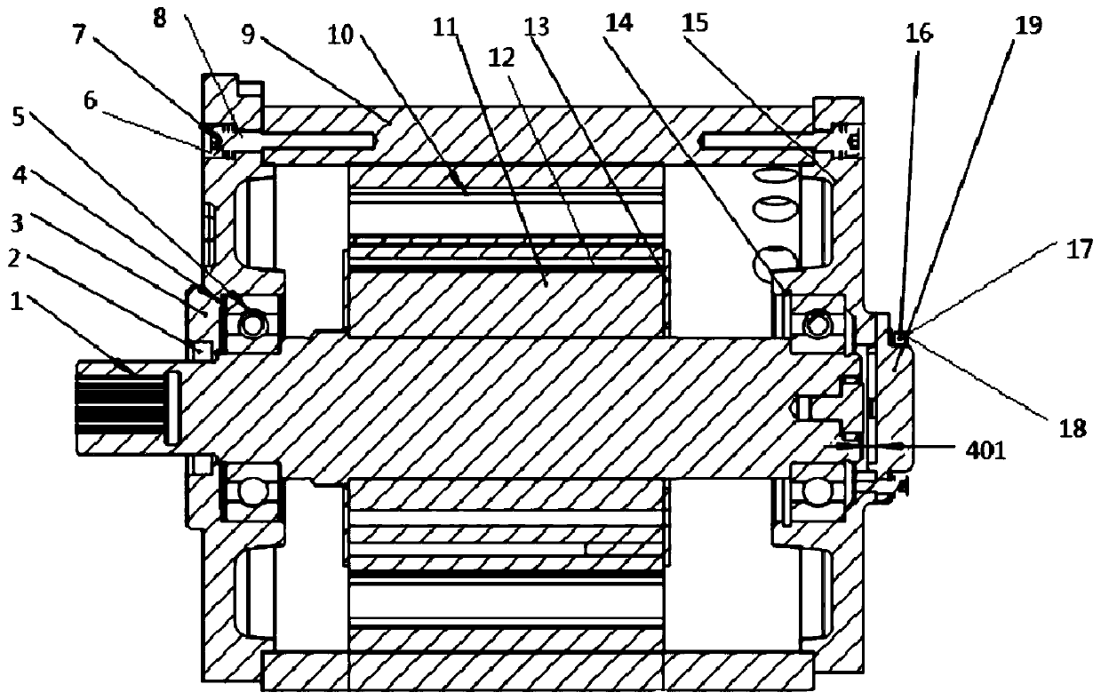
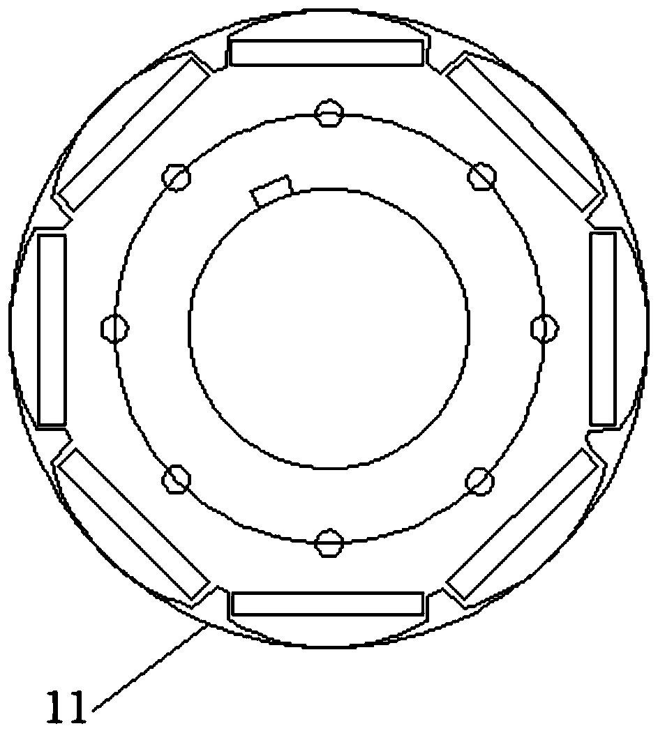
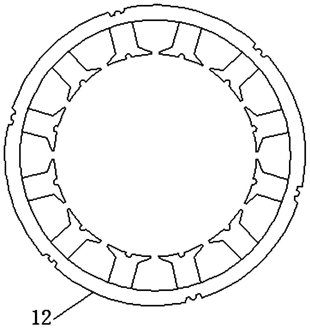
[0027] A permanent magnet synchronous motor, comprising a rotating shaft 1, an end cover 3, a base 9 and a rear cover 15, the two ends of the base 9 are respectively detachably connected with an end cover 3 and a rear cover 15, and the rotating shaft 1 is plugged in Inside the base 9, and the transmission output end of the rotating shaft 1 protrudes from the end cover 3, the inside of the base 9 is respectively equipped with a winding stator 10, a permanent magnet 11 and a rotor core 12, the permanent magnet 11 and the rotor core 12 Located inside the winding stator 10.

[0028] The end cover 3 is detachably connected to the base 9 through the No. 1 fastener 6, the No. 2 fastener 7 and the No. 3 fastener 8 respectively, and the No. 1 fastener 6, the No. The No. 3 fastener 8 facilitates the installation and removal of the end cover 3 and the base 9 .

[0029] A rotating shaft lip seal ring 2 is installed at the joint between the rotating shaft 1 and the end cover 3 , and the w...

Embodiment 2

[0036] A permanent magnet synchronous motor, comprising a rotating shaft 1, an end cover 3, a base 9 and a rear cover 15, the two ends of the base 9 are respectively detachably connected with an end cover 3 and a rear cover 15, and the rotating shaft 1 is plugged in Inside the base 9, and the transmission output end of the rotating shaft 1 protrudes from the end cover 3, the inside of the base 9 is respectively equipped with a winding stator 10, a permanent magnet 11 and a rotor core 12, the permanent magnet 11 and the rotor core 12 Located inside the winding stator 10.

[0037] The end cover 3 is detachably connected to the base 9 through the No. 1 fastener 6, the No. 2 fastener 7 and the No. 3 fastener 8 respectively, and the No. 1 fastener 6, the No. The No. 3 fastener 8 facilitates the installation and removal of the end cover 3 and the base 9 .

[0038] A rotating shaft lip seal ring 2 is installed at the joint between the rotating shaft 1 and the end cover 3 , and the w...


PUM


Abstract

The invention discloses a permanent magnet synchronous motor. The motor comprises a rotating shaft, an end cover, a base and a rear cover, the two ends of the base are detachably connected with an endcover and a rear cover correspondingly. The rotating shaft is inserted into the base; the transmission output end of the rotating shaft protrudes out of the end cover; a winding stator, a permanent magnet and a rotor iron core are installed in the base. According to the permanent magnet synchronous motor, the motor is light in weight, high in release efficiency, good in motor stability and heat dissipation performance and large in starting torque, electric energy can be generated spontaneously under the condition of no external force energy, certain energy recovery is guaranteed, and therefore the effective endurance mileage is increased. On the basis of a traditional motor, one battery pack is reduced, the same continuous mileage is achieved, after matching of the motor and the controller is completed, the cost of the whole vehicle is reduced, and the performance of the whole vehicle is improved.

Description

technical field [0001] The invention relates to the technical field of drive motors for trucks and cars, in particular to a permanent magnet synchronous motor. Background technique [0002] New energy vehicles refer to the use of unconventional vehicle fuels as power sources (or the use of conventional vehicle fuels, the use of new vehicle power devices), integrated vehicle power control and advanced technology in driving, the formation of advanced technical principles, with Automobiles with new technology and new structure. [0003] In the field of new energy vehicles, the driving motor and how to increase the mileage are eternal topics in the industry. Many companies have conducted in-depth research on reducing the weight of the vehicle body or the entire vehicle, that is, the lightweight of the vehicle body. The number of blocks increases the battery capacity, improves the battery density and the battery control system (BMS) system to achieve the mileage of the whole veh...

Claims


Application Information

Patent Timeline
IPC IPC(8): H02K5/167H02K5/124H02K11/215
CPCH02K5/124H02K5/1672H02K11/215
Inventor 葛正军
Owner 衡水斑马汽车研发有限公司
Why Eureka
Try Eureka