Highly Modular Cylindrical Multiphase Permanent Magnet Linear Motor

A permanent magnet linear motor, modular technology, applied in the direction of electromechanical devices, electrical components, electric components, etc., can solve the problems of difficult modular design of motors, difficult fault isolation, high degree of electromagnetic coupling between phases, and achieve good magnetic isolation. Effect, low cost of manufacturing and maintenance, high power density effect

Active Publication Date: 2018-12-14
HARBIN INST OF TECH
View PDF6 Cites 0 Cited by
  • Summary
  • Abstract
  • Description
  • Claims
  • Application Information

AI Technical Summary

Problems solved by technology

[0004] The purpose of the present invention is to solve the problem of difficulty in fault isolation when a fault such as winding short circuit occurs in a conventional multiphase permanent magnet linear motor, and the difficulty in modular design of the motor due to the high degree of electromagnetic coupling between phases, and provides a high-level module Cylindrical Multiphase Permanent Magnet Linear Motor

Method used


Image

  • Highly Modular Cylindrical Multiphase Permanent Magnet Linear Motor
  • Highly Modular Cylindrical Multiphase Permanent Magnet Linear Motor
  • Highly Modular Cylindrical Multiphase Permanent Magnet Linear Motor

Examples


specific Embodiment approach 1

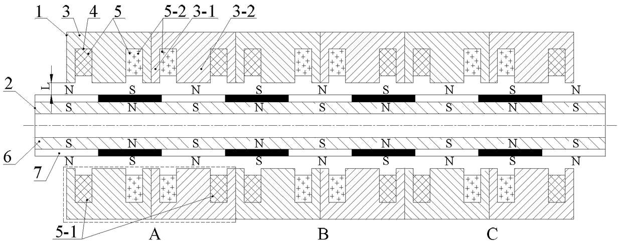
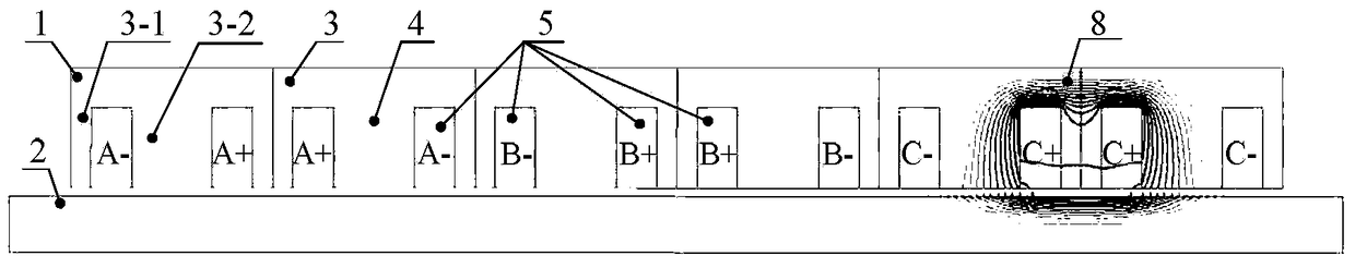
[0017] Specific implementation mode one: the following combination figure 1 and figure 2 Describe this embodiment, the highly modular cylindrical multi-phase permanent magnet linear motor described in this embodiment includes a stator 1 and a permanent magnet mover 2, the stator 1 is arranged inside or outside the permanent magnet mover 2, and There is an air gap of length L between the two;

[0018] The stator 1 is assembled from 2m stator modules, m is the phase number of the motor, and the 2m stator modules are assembled into a cylindrical stator 1 along the axial direction;

[0019] Each stator module includes a stator core 3 and an annular concentrated winding 5; the annular concentrated winding 5 includes two sets of windings: a first annular concentrated winding 5-1 and a second annular concentrated winding 5-2;

[0020] The stator core 3 is provided with two stator slots 4, both the stator core 3 and the stator slot 4 are annular, and the stator slot 4 faces the per...

specific Embodiment approach 2

[0026] Embodiment 2: This embodiment further explains Embodiment 1, m≥3, and the annular concentrated winding 5 is a concentrated winding of three phases or more.

[0027] The use of multi-phase windings can improve the fault-tolerant operation performance of the highly modular cylindrical multi-phase permanent magnet linear motor.

specific Embodiment approach 3

[0028] Embodiment 3: In this embodiment, Embodiment 1 is further described. The stator core 3 is made of silicon steel sheet, amorphous ferromagnetic composite material or SMC soft magnetic composite material.

[0029] The mover core 6 is made of solid steel, silicon steel sheet, amorphous ferromagnetic composite material or SMC soft magnetic composite material.


PUM


Abstract

The invention belongs to the field of permanent magnet motors, and relates to a highly-modularized cylindrical multiphase permanent magnet linear motor. The problems that when a winding short circuit and other failures happen to a conventional multiphase permanent magnet linear motor, the failure isolation difficulty is large, and motor modular design difficulty is large due to the high interphase electromagnetic coupling degree are solved. The highly-modularized cylindrical multiphase permanent magnet linear motor comprises a stator and a permanent magnet rotor, the stator can be arranged inside or outside the permanent magnet rotor, and an air gap exists between the stator and the permanent magnet rotor. The stator is formed by assembling 2m stator modules. The stator modules are assembled to be cylindrical in the axial direction. Each stator module comprises a stator iron core, an armature tooth, two fault-tolerant teeth and two annular concentrated windings. A one-phase module of the highly-modularized cylindrical multiphase permanent magnet linear motor is composed of two adjacent stator modules. The permanent magnet rotor is formed by assembling a permanent magnet and a rotor iron core, and the permanent magnet rotor can be of a surface-mounted structure or a Halbach structure or an axial magnetization structure and the like.

Description

technical field [0001] The invention relates to a modular multiphase permanent magnet fault-tolerant motor, which belongs to the field of permanent magnet motors. Background technique [0002] Since the 21st century, with the increasingly serious energy crisis and environmental pollution, energy conservation and environmental protection have gradually become the two major themes of today's automobile development, and new energy vehicles represented by hybrid vehicles have gained more and more attention. According to the different drive system structures, hybrid electric vehicles can be divided into three types: serial, parallel and hybrid. In the series hybrid electric vehicle, the free piston engine is combined with the linear motor to form a free piston linear power generation system, which replaces the traditional piston internal combustion engine based on the crankshaft connecting rod mechanism, and realizes high efficiency and low emission of the internal combustion eng...

Claims


Application Information

Patent Timeline
Patent Type & Authority Patents(China)
IPC IPC(8): H02K41/03
Inventor 刘勇隋义张书宽杨康范雨卉
Owner HARBIN INST OF TECH
Why Eureka
Try Eureka