Non-invasive equipment operation condition monitoring system and monitoring method thereof

A technology of equipment operation and monitoring system, applied in the direction of measuring device, machine/structural component testing, visible signal device, etc., can solve the problems of inconvenient access to the monitoring system, no software for equipment, and poor operability, etc., to achieve The effect of reducing operational risk, strong versatility, and strong safety

Inactive Publication Date: 2020-03-31
合肥市正茂科技有限公司
View PDF5 Cites 0 Cited by
  • Summary
  • Abstract
  • Description
  • Claims
  • Application Information

AI Technical Summary

Problems solved by technology

[0003] 1. The types of information system equipment are relatively complex, and different solutions are customized for each type of equipment, which is costly and not easy to operate;
[0004] 2. Excessive reliance on software. If the monitored information system has abnormal equipment software, it cannot be monitored normally; some equipment does not have software, such as power sockets;
[0005] 3. The intrusion is too strong, requiring the monitoring system and the monitored information system to be in the same network environment or connected to each other, which increases the risk of system operation, and does not rule out the design and installation defects of the monitoring system, which will affect the monitored information system;
[0006] 4. Part of the equipment needs to pass the verification of the relevant unit before the generated data can be used as valid data (such as traffic speed radar). After the verification, the external interface will be sealed. At this time, it is not convenient to connect to the monitoring system. If it is not included in the monitoring system, it will not meet the verification process, and it is not conducive to the later upgrade of the monitoring system

Method used


Image

  • Non-invasive equipment operation condition monitoring system and monitoring method thereof

Examples


Embodiment Construction

[0026] The present invention will be further described below in conjunction with accompanying drawing:

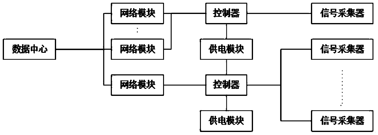
[0027] Such as figure 1 A non-intrusive equipment operation monitoring system, the monitoring system is set independently of the target equipment and is installed in the system for non-interactive use with the target equipment's own software and for collecting physical signals of the equipment under inspection A signal collector, the signal output port of the signal collector is connected to a controller, the output port of the controller is connected to a network module, and the network module is connected to the data center through signal data.

[0028] The signal collector is used to collect abnormal signals sent by the inspected equipment. The signals generally include the light signal of the alarm lamp issued by the alarm, the sound signal of the alarm lamp, the abnormal electromagnetic signal generated by the inspected equipment, and the abnormal temperature signal ge...


PUM


Abstract

The invention discloses a non-invasive equipment operation condition monitoring system and a monitoring method thereof. The monitoring system is independent of target equipment, and a signal collectorwhich is used for realizing non-interactive use with software of the target equipment and is used for collecting physical signals of detected equipment is installed in the system. A signal output port of the signal collector is connected with a controller, an output port of the controller is connected with a network module, and the network module is connected with a data center through signal data. According to the invention, through the arrangement of the detection line independent of the software of the target equipment, the non-interactive use characteristic of the detection line and the target equipment is realized, and the detected equipment is effectively monitored in combination with the signal collector capable of identifying the physical signal.

Description

technical field [0001] The invention relates to the technical field of equipment information monitoring, in particular to a non-invasive equipment operation monitoring system and a monitoring method thereof. Background technique [0002] At present, the monitoring of the operation status of information system equipment generally relies on the interaction with the software that comes with the same equipment. For example, the ping command is used to confirm whether the equipment is online, and the equipment actively reports the operation status. This solution has the following disadvantages [0003] 1. The types of information system equipment are relatively complex, and different solutions are customized for each type of equipment, which is costly and not easy to operate; [0004] 2. Excessive reliance on software. If the monitored information system has abnormal equipment software, it cannot be monitored normally; some equipment does not have software, such as power sockets;...

Claims


Application Information

Patent Timeline
Patent Type & Authority Applications(China)
IPC IPC(8): G01M99/00G08B5/36
CPCG01M99/00G01M99/002G08B5/36
Inventor 吕强吕建春郑刚王晨杨
Owner 合肥市正茂科技有限公司
Why Eureka
Try Eureka