Electric energy transmission system and method based on Internet of Things and Ethernet

A power transmission system and Ethernet technology, applied in the field of power transmission systems based on the Internet of Things and Ethernet, can solve the problems of large and complicated information in the dispatching and monitoring center, which is not conducive to the rapid identification of information by power companies, and facilitate mass production and transmission The effect of fast speed and guaranteed accuracy

Inactive Publication Date: 2020-03-31
温州商学院
View PDF0 Cites 0 Cited by
  • Summary
  • Abstract
  • Description
  • Claims
  • Application Information

AI Technical Summary

Problems solved by technology

For a large-scale transmission network, the information received by the dispatch monitoring center is too large and complicated, which is not conducive to the rapid identification of information by power companies

Method used


Image

  • Electric energy transmission system and method based on Internet of Things and Ethernet
  • Electric energy transmission system and method based on Internet of Things and Ethernet
  • Electric energy transmission system and method based on Internet of Things and Ethernet

Examples


Embodiment 1

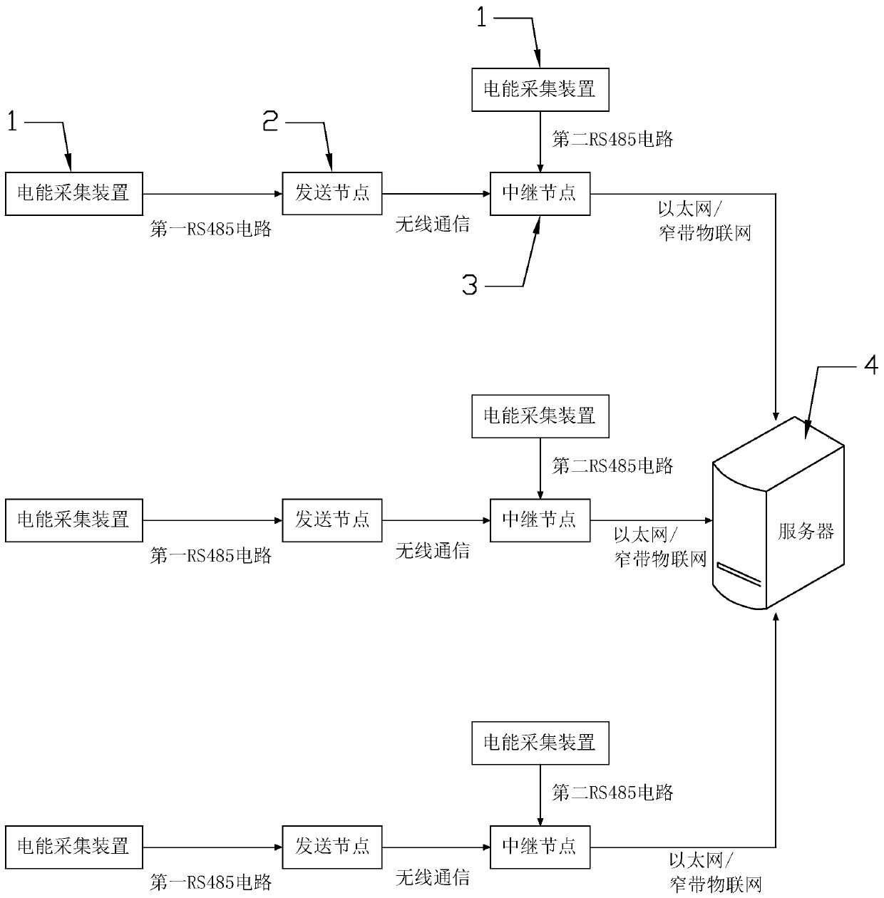
[0053] Such as Figure 1-3 As shown, in the embodiment of the present invention, a power transmission system based on the Internet of Things and Ethernet is proposed, including:

[0054] Several power collection devices 1 for obtaining power quality information;

[0055] A sending node 2 corresponding to each electric energy collection device 1 one by one, and each sending node 2 is used to send the power quality information collected by the corresponding electric energy collection device 1;

[0056] A relay node 3 for receiving the power quality information sent by each sending node 2;

[0057] And a server 4 that is connected to each relay node 3 and summarizes the power quality information sent by each relay node 3; wherein,

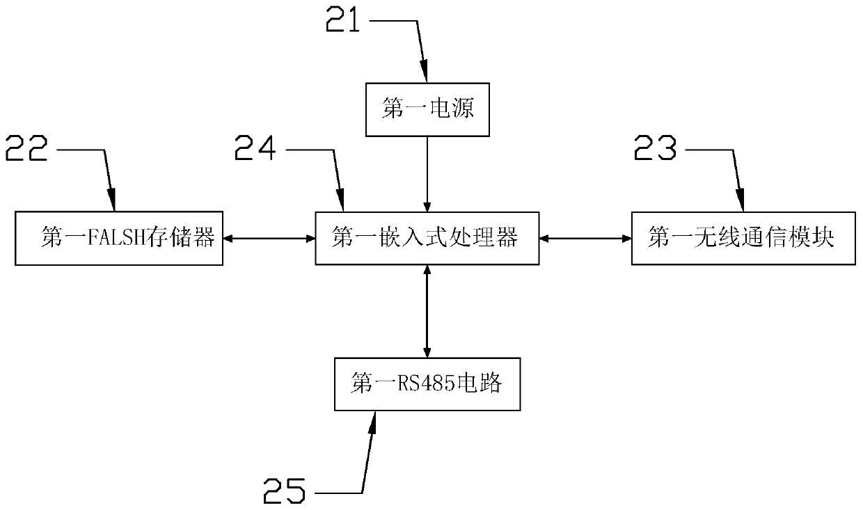
[0058] The sending node 2 includes a first power supply 21 and a first embedded processor 24 powered by the first power supply 21, a first FLASH memory 22, a first wireless communication module 23 and a first RS485 circuit 25, the first embedded pro...

Embodiment 2

[0064] Such as Figure 4-6 As shown, in the embodiment of the present invention, a proposed method of power transmission based on the Internet of Things and Ethernet includes the following steps:

[0065] Step S1, placing a power collection device 1 at each power quality collection point, and obtaining corresponding power quality information;

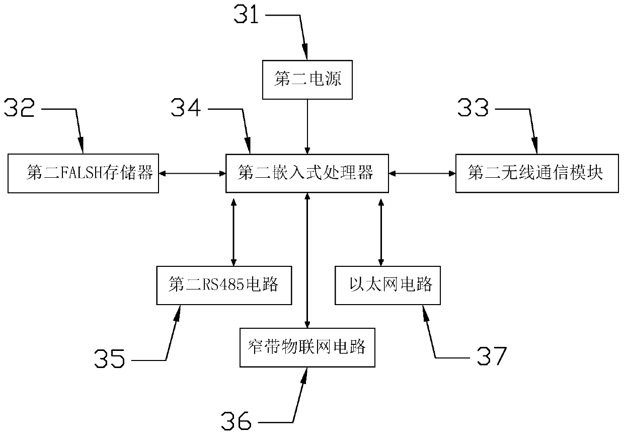
[0066] Step S2, the sending node 2 receives the power quality information collected by each power collection device 1, and detects whether it is the sending node 2; if so, executes step S3; if not, then judges that the sending node 2 is a relay node 3 , storing the collected power quality information into the second FLASH memory 32, and executing step S4;

[0067] Step S3, the sending node 2 sends the collected power quality information to the relay node 3 via Ethernet, and the relay node 3 stores the collected power quality information into the second FLASH memory 32;

[0068] Step S4, the relay node 3 reads the power quality informa...


PUM


Abstract

The invention discloses an electric energy transmission system based on the Internet of Things and the Ethernet. The electric energy transmission system comprises electric energy collection devices, sending nodes in one-to-one correspondence with the electric energy collection devices, relay nodes used for receiving electric energy quality information sent by the sending nodes, and a server connected with the relay nodes. The sending node comprises a first power supply, and a first embedded processor, a first FLASH memory, a first wireless communication module and a first RS485 circuit which are powered by the first power supply; the relay node comprises a second power supply, and a second embedded processor, a second FLASH memory, a second wireless communication module, an Ethernet circuit and a narrowband Internet of Things circuit which are powered by the second power supply, and the Ethernet circuit and the narrowband Internet of Things circuit are connected with the server so as to be used for transmitting each part of power quality information to the server. The method has the beneficial effects that the electric energy information transmission mode can be switched accordingto the actual situation, and scientific and effective scheduling is implemented.

Description

technical field [0001] The invention relates to the technical field of the Internet of Things, in particular to an electric energy transmission system and method based on the Internet of Things and Ethernet. Background technique [0002] In recent years, the scale of power grids has continued to expand, and the planning and practice of smart grids has expanded on a large scale. For such a large-scale power grid, one of the key indicators to evaluate its economic benefits and production safety performance is the quality of electric energy. Power with better quality can not only make the user's electrical equipment work reliably, but also provide energy for the grid. Running a business brings considerable economic benefits. For the whole society, with the development of the economy, people's requirements for the level of power quality are also increasing. [0003] At the same time, with the progress and improvement of the Internet of Things, its related technologies are wide...

Claims


Application Information

Patent Timeline
IPC IPC(8): G06Q50/06H02J13/00H04L29/08
CPCG06Q50/06H04L67/12Y04S40/124Y04S40/126Y04S40/128Y02E60/00
Inventor 沈良忠
Owner 温州商学院
Why Eureka
Try Eureka