Guide carriage having a piezoresistive layer for load measurement

A piezoresistor and sliding seat technology, which is applied in the measurement of the property force of the piezoelectric resistive material, the measuring device, the force/torque/power measuring instrument, etc., can solve the problem of breakdown, high impedance, unsuitable for measuring static stress, etc. Problems, to achieve the effect of favorable cost and reduced consumption

Active Publication Date: 2020-03-31
ROBERT BOSCH GMBH
View PDF13 Cites 0 Cited by
  • Summary
  • Abstract
  • Description
  • Claims
  • Application Information

AI Technical Summary

Problems solved by technology

Furthermore, piezoelectric sensors, i.e. sensors that generate a voltage under the action of an external load, are not suitable for measuring static stress
Its impedance is so high that the piezo voltage immediately breaks down when the piezo sensor is loaded with an ohmic load

Method used


Image

  • Guide carriage having a piezoresistive layer for load measurement
  • Guide carriage having a piezoresistive layer for load measurement
  • Guide carriage having a piezoresistive layer for load measurement

Examples


Embodiment Construction

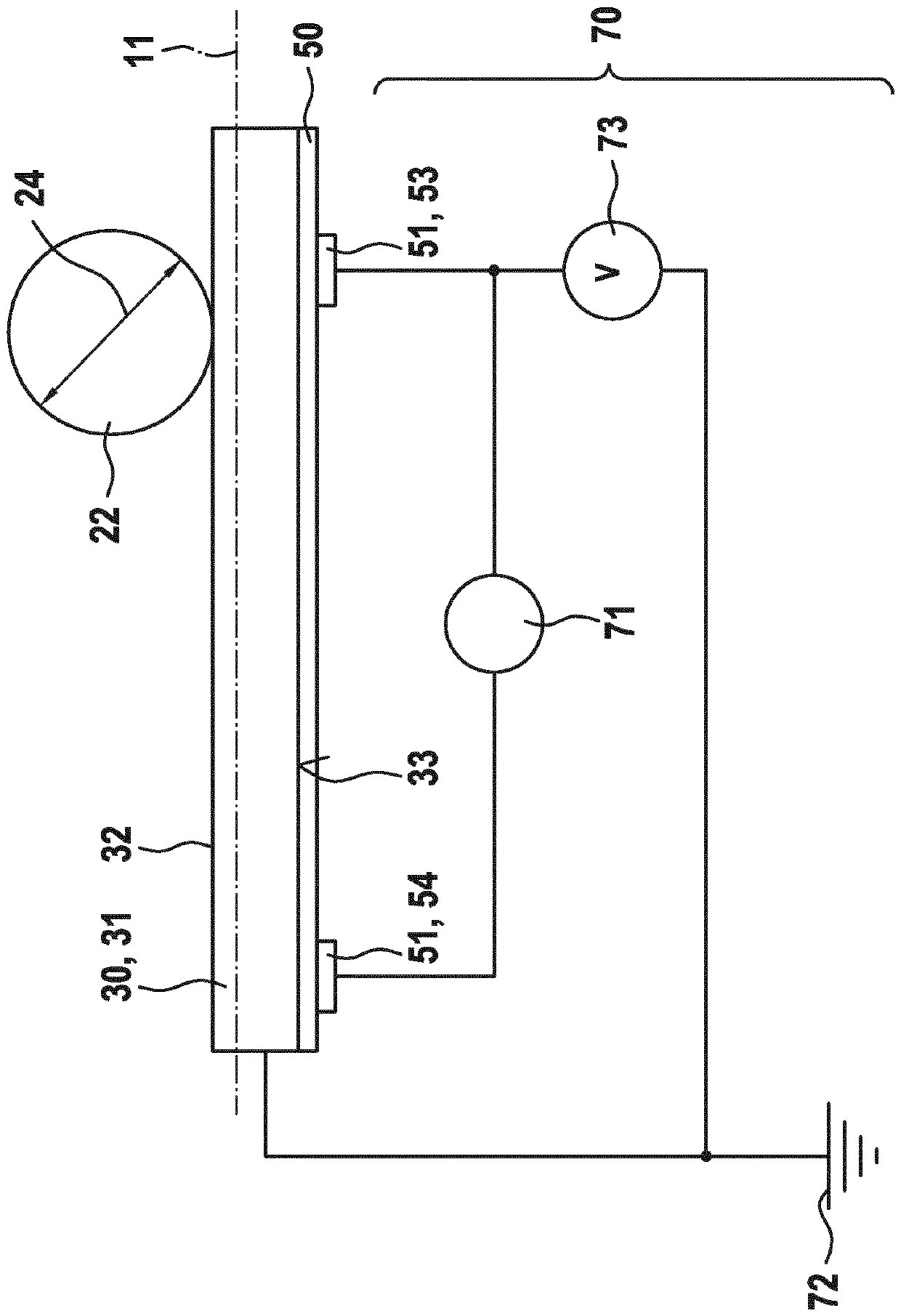
[0030] figure 1A cross-section of a linear rolling bearing 10 with a guide carriage 20 according to the invention is shown. In this case, the guide carriage 20 has four continuous rows of rolling elements 22 , which are designed in the form of rollers. A row of rolling elements 22 is arranged on each raceway insert 30 . The linear rolling bearing 10 is constructed largely according to EP 2 110 571 B1, wherein in particular the raceway insert 30 is glued to the main body 21 . The invention can also be used for guide carriages with ball-shaped rolling elements and for guide carriages without rolling element encirclements.

[0031] The number of rows of rolling bodies can be chosen arbitrarily to a large extent. For example, the invention can also be applied to linear rolling bearings constructed according to EP 2 949 954 B1. Here, ball-shaped rolling elements are provided, wherein two rows of rolling elements are assigned to each raceway insert. The raceway insert rests fri...


PUM

PropertyMeasurementUnit
Average roughnessaaaaaaaaaa

Abstract

The invention relates to a guide carriage (20) for use in a linear roller bearing (10), the guide carriage (20) comprising separate raceway inserts (30) having carriage raceways (32) for the rolling elements (22). According to the invention, the raceway inserts (30) have a piezoresistive layer (50) and electrodes (51) in order to measure an external load on the guide carriage (20).

Description

technical field [0001] The invention relates to a guide carriage according to the preamble of claim 1 . Background technique [0002] A linear rolling bearing with a guide carriage is known from DE 10 2008 051 682 A1. The guide carriage comprises several rows of rolling elements that are continuously surrounding, wherein each row is supported on the main body of the guide carriage in a load-transmitting manner by means of an associated raceway insert. A metal sheet with perforations is arranged between the bearing surface of the raceway insert and the main body, wherein the perforations are filled with adhesive material. A piezoelectric ceramic sensor is arranged in one of the perforations. [0003] The disadvantage of this arrangement is that the load acting on the guide carriage can only be measured imprecisely, since only a small part of the load is transmitted by the piezoceramic sensor. The immediately adjacent metal plates carry most of the load. Furthermore, piezo...

Claims


Application Information

Patent Timeline
IPC IPC(8): G01L5/00
CPCG01L5/0019F16C29/00F16C29/065F16C2233/00F16C2202/36G01L1/18
Inventor J.米尔费尔德M.科巴歇尔G.罗伊辛格M.施托克S.多恩
Owner ROBERT BOSCH GMBH
Why Eureka
Try Eureka