
Pneumatic type multi-glue-barrel dispensing mechanism and dispensing method thereof

A dispensing mechanism, pneumatic technology, applied in the coating, the device for coating liquid on the surface, etc., can solve the problem of affecting the size and thickness of the solder paste, affecting the dispensing accuracy, and inconsistent glue volume, etc., to improve the dispensing Motion accuracy, reducing space occupied area, and ensuring the effect of dispensing quality

Active Publication Date: 2020-04-03
SHENZHEN XINYICHANG TECH CO LTD
View PDF7 Cites 3 Cited by
  • Summary
  • Abstract
  • Description
  • Claims
  • Application Information

AI Technical Summary

Problems solved by technology

[0002] The existing dispensing technology uses a single multi-tube dispensing head to dispense solder paste on the IC bracket. Due to the precision error of the machined parts, the tolerances of each part will accumulate during assembly and assembly, resulting in four points. The glue head is not in the same spatial position. When the dispensing head dispenses glue on the bracket, it will affect the size and thickness of the solder paste on the bracket, resulting in the loss of viscosity or excessive thickness of the solder paste in the chip packaging process; As the paste liquid level drops, the air pressure in it also changes, and there is a hidden danger of unstable glue output from the glue cartridge, resulting in inconsistent shapes and sizes of solder paste on the bracket, which affects the dispensing accuracy of the overall machine.
Moreover, the traditional structure of the dispensing head does not have the function of reflecting its status information. When the operator debugs the machine and replaces the dispensing head, he often can only correct the position of the dispensing head based on experience and feeling, and the dispensing of each adjustment The position of the head will be different, resulting in the inconsistent amount of glue on the bracket, and the product consistency is not good

Method used


Image

  • Pneumatic type multi-glue-barrel dispensing mechanism and dispensing method thereof
  • Pneumatic type multi-glue-barrel dispensing mechanism and dispensing method thereof
  • Pneumatic type multi-glue-barrel dispensing mechanism and dispensing method thereof

Examples


Embodiment 1

[0052] Embodiment 1: the concrete structure of the present invention is as follows:

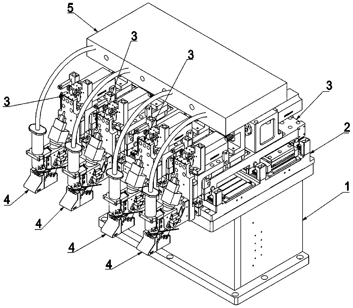
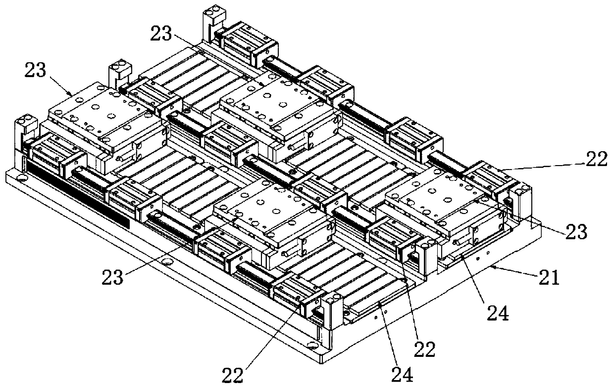
[0053] Please refer to the attached Figure 1-6 , a pneumatic multiple glue cartridge dispensing mechanism of the present invention, the dispensing mechanism includes:

[0054] Column platform 1;

[0055] Multiple sets of linear drive components 2 installed on the top of the column platform 1 and arranged horizontally;

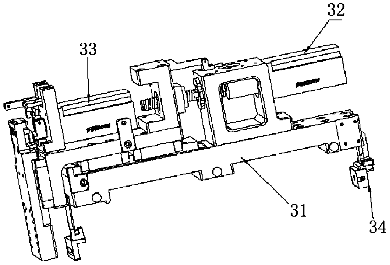
[0056] Multiple groups of dispensing units 3 are installed on the movable part of the linear drive assembly 2 and are driven by the linear drive assembly 2 to move in the X-axis;

[0057] The dispensing manipulator 4 is installed on the front end of the dispensing unit 3 and can be driven by the dispensing unit 3 to perform lifting motion and Y-axis movement. The dispensing manipulator 4 is provided with upper and lower contacts and a dispensing head , the dispensing manipulator 4 transmits electrical signals by closing and disconnecting the upper and lower contacts, and t...

Embodiment 2

[0081] A dispensing method of a pneumatic multiple glue cartridge dispensing mechanism, the method comprising the following steps:

[0082] Step 1, at first, the dispensing manipulator 4 is driven by the system of the left and right linear drive components 2 and the dispensing unit 3, so that each dispensing manipulator 4 reaches directly above the desired dispensing support;

[0083] Step 2, then, the camera lens assembly 42 in the glue dispensing manipulator 4 takes pictures of the bracket to identify, and the camera lens assembly 42 assists the system to drive the bracket to move to the collagen dispensing point;

[0084] Step 3, then, the dispensing control box 5 controls the solenoid valve to apply pressure to the rubber cartridge, and the system drives the dispensing manipulator 4 to move downward to dispens the bracket;

[0085] Step 4. Finally, the dispensing area of ​​each dispensing manipulator 4 is determined through system programming, and multiple dispensing manip...


PUM


Abstract

The invention discloses a pneumatic type multi-glue-barrel dispensing mechanism and a dispensing method thereof. The mechanism comprises a stand column platform, a linear drive assembly, multiple dispensing units, multiple dispensing mechanical hands and a dispensing control box. The linear drive assembly which is transversely arranged is laid flat on the stand column platform. The multiple dispensing units which independently move leftwards and rightwards are arranged on the linear drive assembly. Each dispensing mechanical hand capable of being regulated up and down is arranged at the frontend of the corresponding dispensing unit. Glue barrels on the dispensing mechanical hands are connected with the dispensing control box through gas pipes. The multiple dispensing mechanical hands in the pneumatic type multi-glue-barrel dispensing mechanism can conduct dispensing on a support while doing multidimensional independent movement in the X direction, the Y direction and the Z direction,contact assemblies of the dispensing mechanical hands transmit electrical signals through closing and opening of upper contacts and lower contacts, the relative height of dispensing heads is confirmedthrough the electrical signals, the pressure in the glue barrels can be regulated through the dispensing control box, glue discharged from the dispensing heads can keep consistent micro glue sizes and shapes, and the dispensing speed and precision are remarkably increased.

Description

technical field [0001] The invention relates to the technical field of semiconductor packaging, in particular to a pneumatic multi-glue cartridge dispensing mechanism and a dispensing method for a solder paste dispensing process. Background technique [0002] The existing dispensing technology uses a single multi-tube dispensing head to dispense solder paste on the IC bracket. Due to the precision error of the machined parts, the tolerances of each part will accumulate during assembly and assembly, resulting in four points. The glue head is not in the same spatial position. When the dispensing head dispenses glue on the bracket, it will affect the size and thickness of the solder paste on the bracket, resulting in the loss of viscosity or excessive thickness of the solder paste in the chip packaging process; As the paste liquid level drops, the air pressure in it also changes, and there is a hidden danger of unstable glue output from the glue cartridge, resulting in inconsis...

Claims


Application Information

Patent Timeline
Patent Type & Authority Applications(China)
IPC IPC(8): B05C5/02B05C11/10
CPCB05C5/02B05C11/10B05C11/1013B05C11/1018
Inventor 胡新荣
Owner SHENZHEN XINYICHANG TECH CO LTD
Learn More