
Laser marking device

A laser marking and laser technology, applied in the laser field, can solve the problems of poor infrared laser marking effect, etc., and achieve stable and reliable marking effect.

Active Publication Date: 2020-04-03
HANS LASER TECH IND GRP CO LTD
View PDF13 Cites 2 Cited by
  • Summary
  • Abstract
  • Description
  • Claims
  • Application Information

AI Technical Summary

Problems solved by technology

[0006] The main purpose of the present invention is to provide a laser marking device to solve the technical problem of poor infrared laser marking effect in the prior art

Method used


Image

  • Laser marking device
  • Laser marking device
  • Laser marking device

Examples


Embodiment Construction

[0031] In order to make the purpose, features and advantages of the present invention more obvious and understandable, the technical solutions in the embodiments of the present invention will be clearly and completely described below in conjunction with the accompanying drawings in the embodiments of the present invention. Obviously, the described The embodiments are only some of the embodiments of the present invention, but not all of them. Based on the embodiments of the present invention, all other embodiments obtained by those skilled in the art without making creative efforts belong to the protection scope of the present invention.

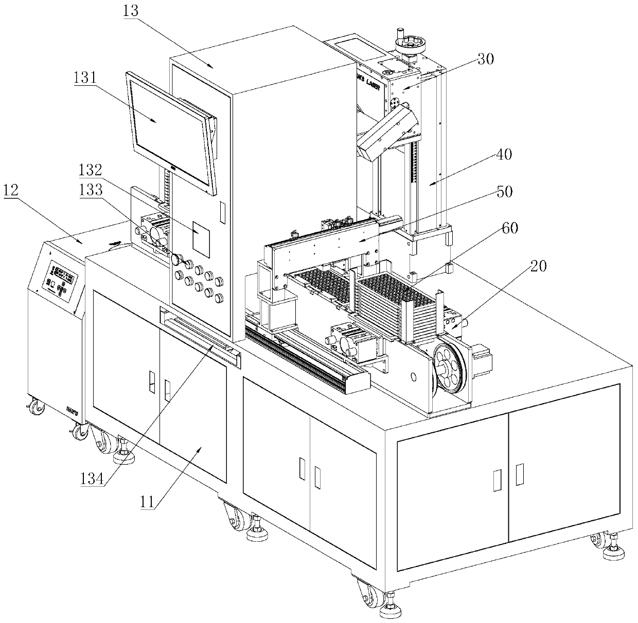
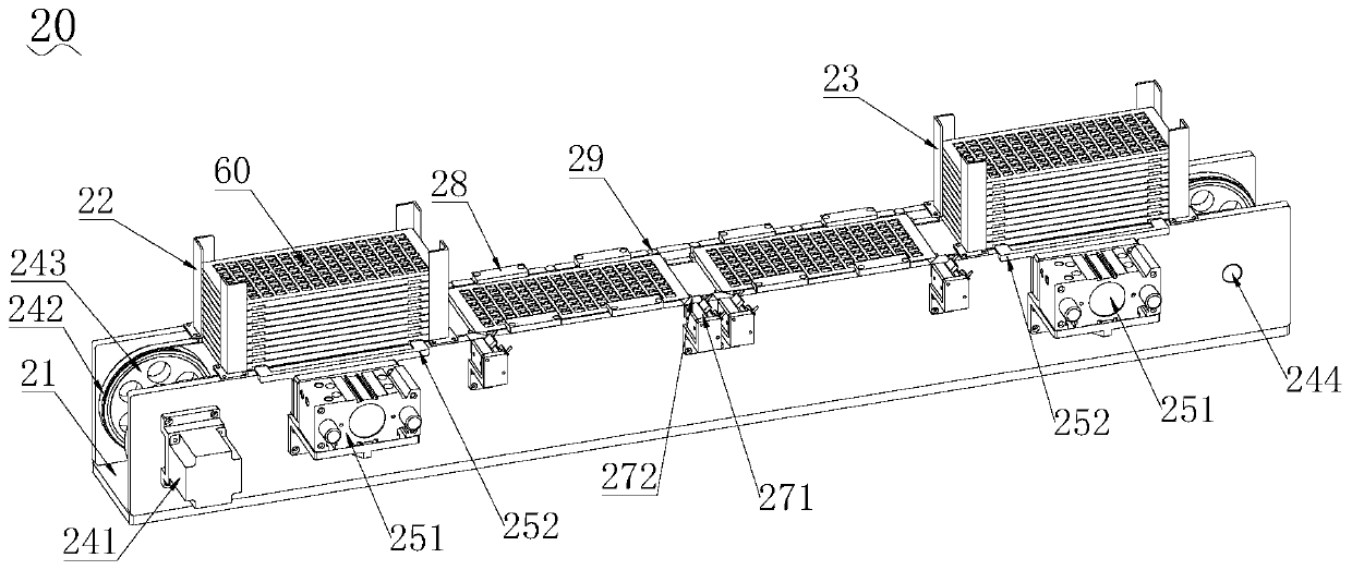
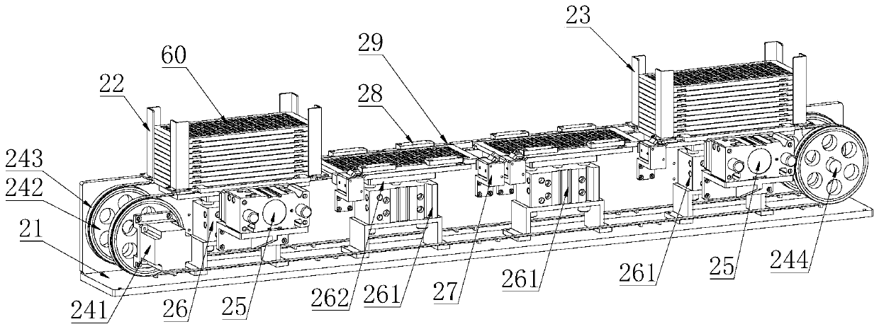
[0032] see figure 1 and figure 2 , a laser marking device, comprising: a cabinet 11, a loading and unloading assembly 20, a marking assembly 30, and a lifting assembly 40; the loading and unloading assembly 20 and the lifting assembly 40 are arranged on the cabinet 11, and the marking assembly 30 is arranged on the lifting assembly 40 And ...


PUM


Abstract

The invention discloses a laser marking device. The laser marking device comprises a cabinet, a feeding and discharging assembly, a marking assembly and a lifting assembly, wherein the feeding and discharging assembly and the lifting assembly are arranged on the cabinet, the marking assembly is arranged on the lifting assembly and positioned above the feeding and discharging assembly, the markingassembly comprises a laser, and the light source of the laser is a green light source. According to the laser marking device, a green-light laser beam is used for focusing on the surface of a productto form fine and high-energy density light spots, each high-energy laser pulse instantaneously breaks molecular bonds on the surface of the processed material to form mark marks, and the pre-designedcharacters, graphics and other contents are permanently marked on the surface of the material, so that the marking effect is stable and reliable, and the permanent mark does not fade. By means of thelaser marking device, the technical problem of poor infrared laser marking effect in the prior art is solved.

Description

technical field [0001] The invention relates to the technical field of lasers, in particular to a laser marking device. Background technique [0002] With the popularization of various electronic cards, the market competition is becoming more and more fierce. Manufacturers have higher and higher requirements for production efficiency, more and more stringent requirements for performance and appearance, and stricter control over production costs. The traditional single-station infrared laser marking method is far from meeting these requirements. The traditional method of IC card marking is to use a single-station infrared laser to mark, but this method of marking IC cards has the following disadvantages: [0003] 1. The effect of infrared laser marking is poor, mainly manifested as uneven line thickness and different depth; the naked eye can see obvious color difference; [0004] 2. There are operational errors in manual feeding, it is difficult to maintain the same accuracy...

Claims


Application Information

Patent Timeline
IPC IPC(8): B23K26/362B23K26/70
CPCB23K26/362B23K26/702Y02P70/50
Inventor 曹洪涛吕启涛胡杰刘亮杨柯黄旭升梁华亮黄龙胡述旭高云峰
Owner HANS LASER TECH IND GRP CO LTD
Learn More