Power transmission line tower surface defect detection method and device based on green laser imaging

A transmission line, laser imaging technology, applied in optical testing flaws/defects, camera devices, radio wave measurement systems, etc. The effect of non-destructive testing

Pending Publication Date: 2022-04-01
STATE GRID HEILONGJIANG ELECTRIC POWER CO LTD ELECTRIC POWER RES INST +1
View PDF6 Cites 0 Cited by
  • Summary
  • Abstract
  • Description
  • Claims
  • Application Information

AI Technical Summary

Problems solved by technology

[0003] However, due to the complex components of transmission line towers and different environmental backgrounds, the existing measurement technology is easy to lose small parts when shooting or modeling, and the effect is often not good. It is difficult to accurately find the defects on the surface of the tower

Method used


Image

  • Power transmission line tower surface defect detection method and device based on green laser imaging
  • Power transmission line tower surface defect detection method and device based on green laser imaging
  • Power transmission line tower surface defect detection method and device based on green laser imaging

Examples


Embodiment 1

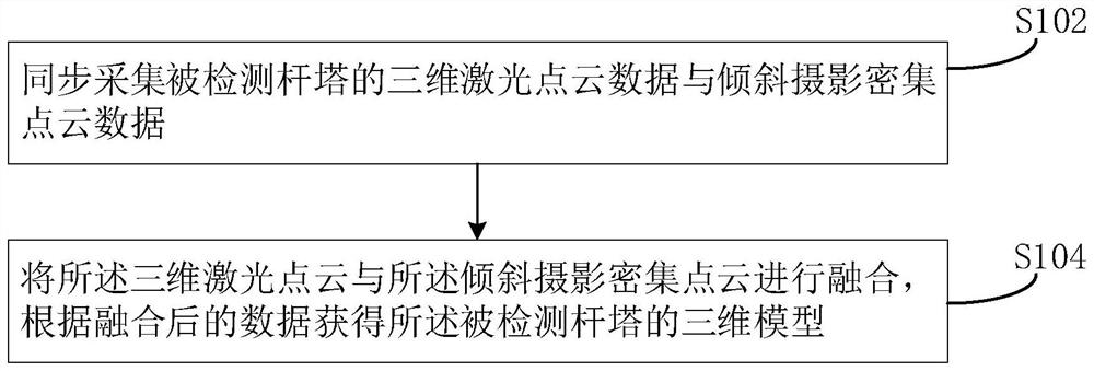
[0049] Such as figure 1 As shown, the embodiment of the present disclosure provides a laser imaging-based transmission line tower modeling method, which specifically includes the following steps:

[0050] Step S102, synchronously collecting 3D laser point cloud data and oblique photography dense point cloud data of the detected tower;

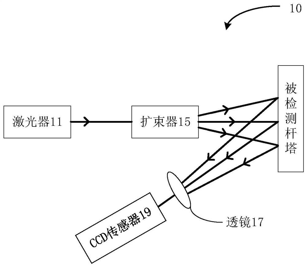
[0051] In this step, the 3D laser point cloud of the detected tower can be collected using a laser imaging system. figure 2 A schematic structural diagram of a laser imaging system 10 that can be used in this embodiment is shown.

[0052] The laser imaging system 10 includes: a laser 11 , a beam expander 15 , a lens 17 and a CCD sensor 19 . The laser beam emitted by the laser 11 is expanded by the beam expander 15 to become uniform divergent light, and the uniform divergent light and scattered light are finally imaged to the CCD sensor 19 through the lens 17 . Specifically, the laser 11 is used to generate detection light; the beam expander...

Embodiment 2

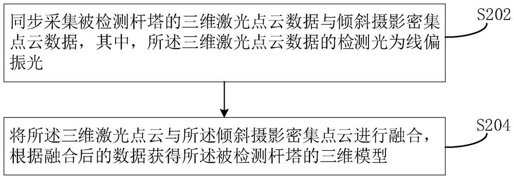
[0069] Such as image 3 As shown, the embodiment of the present disclosure also provides a method for modeling transmission line towers based on polarization laser imaging, which specifically includes the following steps:

[0070] S202. Synchronously collect 3D laser point cloud data and oblique photography dense point cloud data of the detected tower, wherein the detection light of the 3D laser point cloud data is linearly polarized light;

[0071] S204. Fusion the 3D laser point cloud data and the oblique photography dense point cloud data, and obtain a 3D model of the detected tower according to the fused data.

[0072] Different from the foregoing embodiments, linearly polarized light is used as the detection light of the three-dimensional laser point cloud data in this embodiment. Figure 4 A schematic structural diagram of a laser imaging system 20 that can be used in this embodiment is shown.

[0073] The laser imaging system 20 includes: a laser 11 , a polarizer 13 ,...

Embodiment 3

[0078] Such as Figure 5 As shown, the embodiment of the present disclosure also provides a method for modeling transmission line towers based on laser imaging, which specifically includes the following steps:

[0079] S302. Synchronously collect 3D laser point cloud data and oblique photography dense point cloud data of the detected tower, wherein the observation position of the 3D laser point cloud data is located on the ground near the detected tower, and the oblique photography dense point cloud The observation position point of the data is located in the air near the detected tower;

[0080] S304. Fusion the 3D laser point cloud data and the oblique photography dense point cloud data, and obtain a 3D model of the detected tower according to the fused data.

[0081] Different from the previous embodiments, the observation position of the three-dimensional laser point cloud data in this embodiment is located on the ground near the detected tower, while the observation posi...


PUM


Abstract

The invention provides a power transmission line tower surface defect detection method based on green laser imaging. The method comprises the following steps: dividing a detected tower into a plurality of sub-regions; sequentially collecting oblique photography data of each sub-region of the detected tower under the irradiation of the green laser beams; performing image fusion and splicing on the oblique photography data based on a contour line extraction algorithm of region growth; and judging whether the detected tower has defects or not according to the fused and spliced image. According to the transmission line tower surface defect detection method provided by the invention, tiny detail information of the detected tower can be accurately obtained, and nondestructive detection of the tower is realized.

Description

technical field [0001] The present disclosure relates to the technical field of transmission line pole and tower defect detection, in particular, to a method, device, medium and electronic equipment for detecting surface defects of transmission line pole and tower based on green light laser imaging. Background technique [0002] Harsh environments such as high temperature, high pressure, and corrosion will cause irreversible damage to long-term service metal components, especially micro-damages on the surface of metal materials, which are difficult to detect but extremely harmful. Therefore, it is necessary to monitor the surface performance of transmission line towers. The monitoring of transmission line towers usually adopts a non-destructive method. Non-destructive testing technology uses physical or chemical means to find out whether there are problems or defects in the detected object without harming the performance of the detected object and ensuring the integrity of ...

Claims


Application Information

Patent Timeline
Patent Type & Authority Applications(China)
IPC IPC(8): G01N21/88G01C11/36G01C11/02
Inventor 盛杰宫铭辰王文龙张健张航曲利民董德阳贾雯博邢维申昱博周萌
Owner STATE GRID HEILONGJIANG ELECTRIC POWER CO LTD ELECTRIC POWER RES INST
Why Eureka
Try Eureka