
Handheld teaching device and method based on stereoscopic vision
A technology of stereo vision and teaching device, which is applied in the direction of measuring device, manipulator, teaching model, etc., can solve the problems of cumbersome teaching process and long teaching time of robots, so as to improve usability, facilitate image processing and work efficiency. boosted effect
- Summary
- Abstract
- Description
- Claims
- Application Information
AI Technical Summary
Problems solved by technology
Method used
Image

Examples
Embodiment
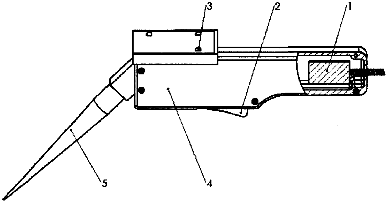
[0020] Example: as attached figure 1 As shown, a robot hand-held teaching device based on stereo vision includes an information sending unit 1, a signal trigger device 2, three light sources 3, a hand-held handle 4, and a pose measuring rod 5; as attached figure 1 In the shown embodiment, the information sending unit 1 is installed inside the hand-held handle 4, and the signal triggering device 2 is fixed on the lower surface of the hand-held handle 4 through a fixing hole; the three light sources 3 are fixed on the hand-held handle 4 upper surface; the pose measuring rod 5 is fixed on the front end of the handle 4 through a fixing hole.
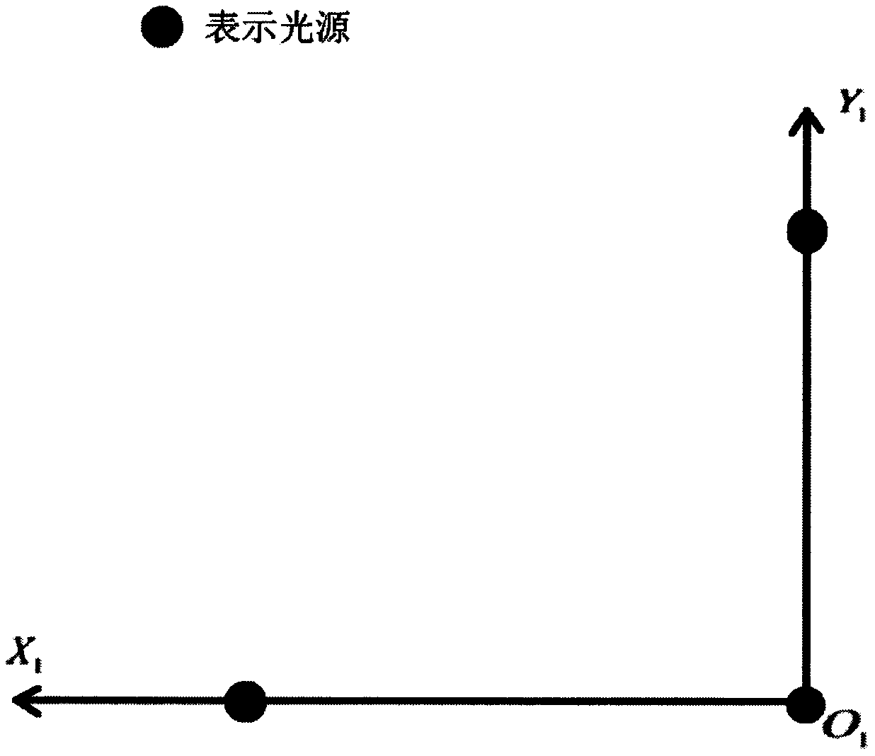
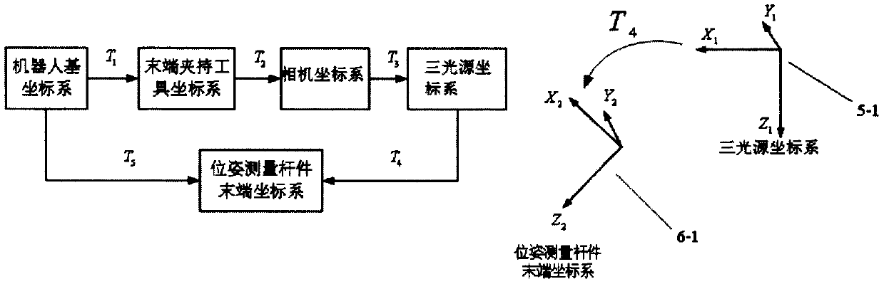
[0021] Such as figure 2 As shown, choose one of the three light sources as the origin O 1 , construct the X-axis and Y-axis respectively with the other two light sources, determine the direction of the Z-axis according to the right-hand rule, and construct three light source coordinate systems 5-1. Let the position information of the thr...
PUM
 Abstract
Description
Claims
Application Information