Glass kettle forming device and forming process

A molding device and molding process technology, applied in the field of glass pot molding device and molding process, can solve the problems of unsightly appearance, low yield, rigid appearance lines, etc., and achieve the effects of simple production process, technical problem solving and high practical value.

Active Publication Date: 2020-04-03
SHENZHEN ESID DESIGN LTD
View PDF8 Cites 2 Cited by
  • Summary
  • Abstract
  • Description
  • Claims
  • Application Information

AI Technical Summary

Problems solved by technology

After the glass pot body is finished, the spout needs to be processed; the spout of the high borosilicate heat-resistant glass pot currently on the market is usually located on the side of the main body of the glass pot, and the spout manufacturing process is relatively simple; after the main body of the glass pot is made , set the glass spout on the glass jug by blowing and pulling out the shape by fusing the glass rod or the glass tube; The lines are very stiff, unsightly, and the pouring is not smooth enough
The production process of this kind of nozzle is relatively cumbersome, which requires high molding skills and high cost, and most of them are made by hand, which is easy to cause low yield, and the appearance will have certain shortcomings

Method used


Image

  • Glass kettle forming device and forming process
  • Glass kettle forming device and forming process

Examples


Embodiment 1

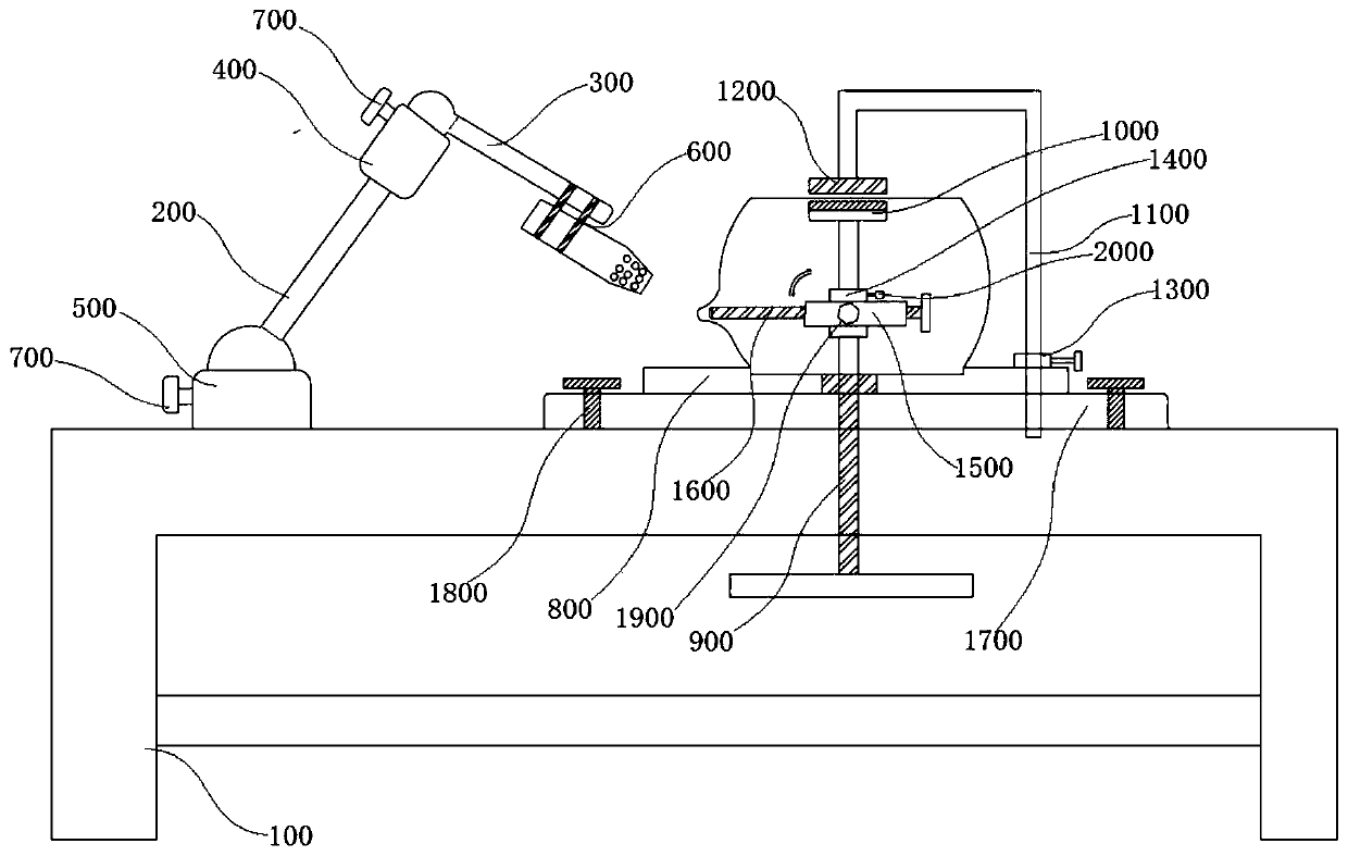
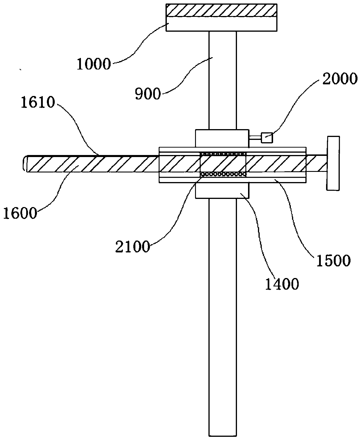
[0028] Such as figure 1 and figure 2As shown, this embodiment provides a glass pot forming device, including a workbench, a positioning device and a pressing device; the workbench includes a three-dimensional frame 100 and a heating adjustment assembly, and the heating adjustment assembly includes a first connecting rod 200 and a second connecting rod 300, the ends of the first connecting rod 200 and the second connecting rod 300 are connected through the first spherical joint 400, and the end of the first connecting rod 200 away from the first spherical joint 400 is connected to the end of the three-dimensional frame 100 through the second spherical joint 500 The first spherical joint 400 and the second spherical joint 500 are provided with an angle adjusting bolt 700 for fixing the first spherical joint 400 or the second spherical joint 500; the end of the second connecting rod 300 away from the first spherical joint 400 is provided with a nozzle installation Frame 600, th...

Embodiment 2

[0036] This embodiment provides a glass pot forming process using a glass pot forming device to solve the smoothness of the connection between the spout and the pot body, so that the spout and the pot body are integrated, which can not only improve the aesthetics but also make the pouring smoother ; Concretely include the following process steps:

[0037] S1. Embryo body positioning and heating angle adjustment: fix the glass embryo body on the workbench with a positioning device, determine the shape position of the spout according to the glass embryo body specifications, and adjust the angle of the torch and the surface area of ​​the glass embryo body to be heated;

[0038] S2. Partial heating: Use a torch to heat the shape of the spout on the surface of the glass embryo to partially soften the surface of the glass embryo;

[0039] S3. Preliminary pressing: use the pressing screw of the pressing device to push out from the glass body, and the pressing screw of the pressing de...


PUM


Abstract

The invention discloses a glass kettle forming device and forming process. The glass kettle forming device comprises a workbench, a positioning device and a jacking device. The glass kettle forming process comprises the steps of blank positioning, heating angle adjustment, local heating, preliminary jacking, stress application jacking, cutting forming and the like. By improving a traditional highborosilicate glass kettle manufacturing process, the glass kettle is more innovative, practical and attractive; compared with fusion techniques, according to the scheme, the connection smoothness of aspout and a kettle body can be improved, the spout and the kettle body are integrated, the attractiveness can be improved, water can be poured more smoothly through the glass kettle, the limitation of the spout manufacturing process of the traditional high borosilicate heat-resisting glass kettle is broken through, the manufacturing process is relatively simple, and the specification and appearance individuation requirements of the spout part are easy to control.

Description

technical field [0001] The invention relates to the technical field of glass pot manufacturing technology, in particular to a glass pot forming device and a forming process. Background technique [0002] Existing glass kettle body forming production line mainly is made up of glass melting furnace box, cutting material device, material guide device, material cake pressing molding and feeding device and glass kettle body forming device. After the glass pot body is made, the spout needs to be processed; the spouts of the high borosilicate heat-resistant glass pots currently on the market are usually located on the side of the main body of the glass pot, and the spout manufacturing process is relatively simple; after the main body of the glass pot is made , the glass spout is set on the glass jug by blowing out the shape by welding the glass rod or the glass tube; The lines appear very stiff, unsightly, and the pouring is not smooth enough. The production process of this kind ...

Claims


Application Information

Patent Timeline
Patent Type & Authority Applications(China)
IPC IPC(8): C03B23/00
CPCC03B23/0086C03B23/0093Y02P40/57
Inventor 苏炜
Owner SHENZHEN ESID DESIGN LTD
Why Eureka
Try Eureka