
Motor rotor position detection circuit and system

A technology for detecting circuits and motor rotors, applied in the field of signal measurement, to improve circuit reliability, enhance anti-interference ability, and achieve balance

Pending Publication Date: 2020-04-03
BEIJING XINGJI RONGYAO SPACE TECH CO LTD +2
View PDF0 Cites 0 Cited by
  • Summary
  • Abstract
  • Description
  • Claims
  • Application Information

AI Technical Summary

Problems solved by technology

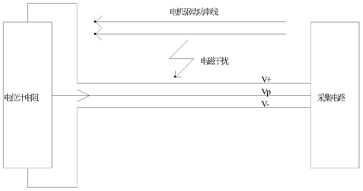
[0005] In view of this, the embodiment of the present invention provides a motor rotor position detection circuit and system to solve the balance problem between position acquisition accuracy and position acquisition noise

Method used


Image

  • Motor rotor position detection circuit and system
  • Motor rotor position detection circuit and system
  • Motor rotor position detection circuit and system

Examples


Embodiment Construction

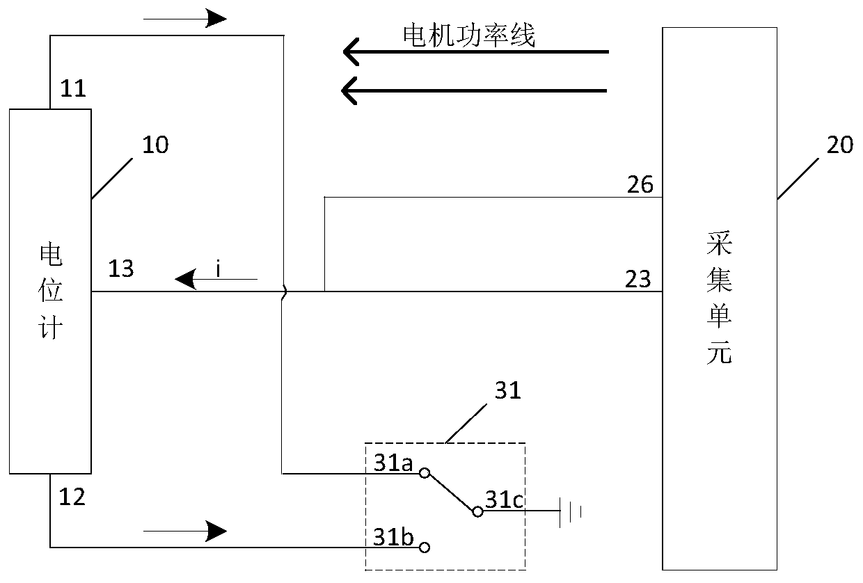
[0046] In order to make the purpose, technical solutions and advantages of the embodiments of the present invention clearer, the technical solutions in the embodiments of the present invention will be clearly and completely described below in conjunction with the drawings in the embodiments of the present invention. Obviously, the described embodiments It is a part of embodiments of the present invention, but not all embodiments. Based on the embodiments of the present invention, all other embodiments obtained by those skilled in the art without making creative efforts belong to the protection scope of the present invention.

[0047]The motor rotor position detection circuit provided by the embodiment of the present invention can be applied to any equipment or system that needs to measure the motor rotor position, for example, it can be applied to industries such as aerospace, weapons, unmanned vehicles, and robots. In the case that the signal line is relatively close to the i...


PUM


Abstract

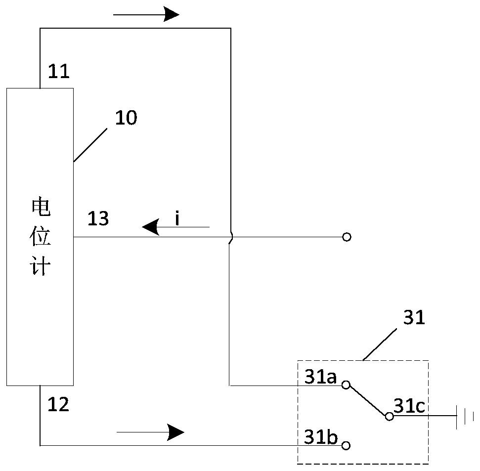
The invention relates to the technical field of signal measurement, and specifically relates to a motor rotor position detection circuit and system, and the circuit comprises at least one potentiometer connected with a to-be-detected motor in a one-to-one correspondence manner; an acquisition unit which comprises at least one group of signal ends corresponding to the potentiometers, wherein the signal ends comprise current output ends and first voltage acquisition ends; the current output ends are connected with taps of the corresponding potentiometers, and the first voltage acquisition endsare connected with taps of the corresponding potentiometers. The circuit also comprises a first selection switch connected with the two ends of each potentiometer and is used for switching the connection between the two ends of each potentiometer and the signal ground. Current is provided for taps of the potentiometers through a current output end in the acquisition unit, and the anti-interference capability of a signal in a strong interference section is enhanced, so that the interference noise is reduced on the premise of not influencing the acquisition precision.

Description

technical field [0001] The invention relates to the technical field of signal measurement, in particular to a detection circuit and system for the position of a motor rotor. Background technique [0002] Motor rotor position detection generally has two purposes: one is that the system as a whole needs motor rotor position information to achieve precise position loop control, such as servo, CNC machine tools or robots, etc.; the other is the need for motor control itself, such as for brushless The DC motor must detect the position of the rotor in order to commutate the stator current so that the rotor can continuously rotate in one direction and achieve the best efficiency. Of course it can also be used to calculate the actual / physical speed of the motor. The accuracy and reliability of rotor position detection is critical for the system's position loop or motor control. [0003] In the prior art, the motor rotor position is generally detected based on the potentiometer res...

Claims


Application Information

Patent Timeline
Patent Type & Authority Applications(China)
IPC IPC(8): G01B7/00G01R31/34H02K11/21
CPCG01B7/003G01R31/346H02K11/21
Inventor 彭小波宋金来
Owner BEIJING XINGJI RONGYAO SPACE TECH CO LTD
Learn More