Optical switch

A technology of optical switch and optical fiber, which is applied in the field of optical communication, can solve problems such as the limitation of the number of optical switch ports, and achieve the effects of increasing the number of ports, expanding the radius of the spot mode field, and increasing the off-axis distance

Pending Publication Date: 2020-04-03
HUAZHONG UNIV OF SCI & TECH +1
View PDF8 Cites 2 Cited by
  • Summary
  • Abstract
  • Description
  • Claims
  • Application Information

AI Technical Summary

Problems solved by technology

[0004] However, due to the constraints of the deflection angle of the MEMS micromirror, the size of the mirror, the focal length of the collimator lens, and the spacing of the fiber array, the number of ports N of the optical switch is limited.

Method used


Image

  • Optical switch
  • Optical switch
  • Optical switch

Examples


Embodiment 1

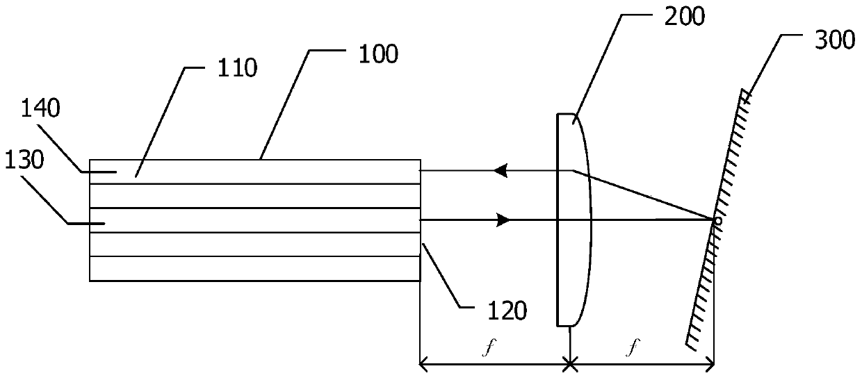
[0036] figure 1 A schematic structural diagram of an optical switch provided in Embodiment 1 of the present invention, as shown in figure 1 As shown, the optical switch provided by Embodiment 1 of the present invention includes: an optical fiber array 100 , a collimator lens 200 and a reflector 300 .

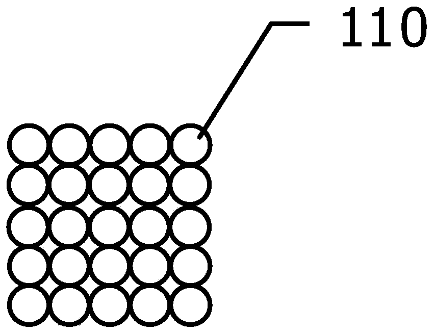
[0037] Wherein, the optical fiber array 100 includes a plurality of optical fibers 110 arranged in a matrix.

[0038] Preferably, as figure 2 As shown, the multiple optical fibers 110 may be arranged in a 5*5 matrix, and in other embodiments, the multiple optical fibers 110 may also be arranged in a 4*4, 3*3, 2*2 or 6*6 matrix, or may be arranged in a 6*4 matrix. *4 Matrix arrangement, which is not limited in this embodiment.

[0039] Further, as image 3 As shown, each optical fiber 110 includes a cladding 111 and a core 112 . The core diameter of the core 112 at the tip portion of the optical fiber 110 is larger than that of other portions. Preferably, the thermal diffu...

Embodiment 2

[0055] Figure 4 It is a schematic structural diagram of an optical switch provided in Embodiment 2 of the present invention. This embodiment is a further refinement of the above technical solution. Such as Figure 4 As shown, the optical switch provided by Embodiment 2 of the present invention includes:

[0056] Figure 4 A schematic structural diagram of an optical switch provided in Embodiment 2 of the present invention, as shown in Figure 4 As shown, the optical switch provided by Embodiment 2 of the present invention includes: an optical fiber array 400 , a collimating lens 500 and a reflecting mirror 600 .

[0057] Such as Figure 5 As shown, the optical fiber array 400 includes a plurality of optical fibers 410 arranged in a matrix. For example, the plurality of optical fibers 410 may be arranged in a matrix of 10*10, 9*9, 8*8, 7*7, 6*6 or 5*5, and in this embodiment, it is arranged in a matrix of 10*10. Preferably, the fiber array 400 is arranged in a glass cap...


PUM


Abstract

The embodiment of the invention provides an optical switch. The optical switch comprises an optical fiber array, a collimating lens and a reflector, the optical fiber array comprises a plurality of optical fibers arranged in a matrix; the fiber core diameter of the front end part of the optical fiber is greater than the fiber core diameters of other parts; the surface of the front end part of theoptical fiber is defined as a front end surface, and the front end surface is arranged at the front focal plane of the collimating lens; and the reflecting mirror is rotatably arranged on the rear focal plane of the collimating lens. An optical signal emitted by the optical fiber is focused to the reflector through the collimating lens, and the optical signal is reflected according to a preset deflection angle of the reflector and then is incident to another optical fiber through the collimating lens. The optical fiber array is composed of a plurality of optical fibers, wherein the fiber corediameters of the front ends of the optical fibers are larger than those of other parts. The mode field radius of the light spot of the emergent light is enlarged, the focal length of the collimating lens is increased under the condition that the size of the mirror surface is kept unchanged, the allowable off-axis distance of the optical fiber on the outermost periphery of the optical fiber array is increased, and therefore the number of ports of the optical switch is increased.

Description

technical field [0001] Embodiments of the present invention relate to the technical field of optical communication, and in particular, to an optical switch. Background technique [0002] An optical switch is a multi-port passive optical device that can control optical signals to switch between multiple optical fiber input / output ports, and is widely used in optical fiber communication systems. With the intelligent development of optical fiber communication networks, the market demand for optical switches is growing rapidly. [0003] At present, in the prior art, optical switches are divided according to the number of ports, and there are simple 1×2 and 2×2 port optical switches. In optical fiber communication systems, they are mainly used for protection switching of optical fiber lines, and their technical solutions are mainly mechanical Optical switch, which switches the light path by driving a prism or mirror through a micro relay. Large-scale N×N port optical switches a...

Claims


Application Information

Patent Timeline
Patent Type & Authority Applications(China)
IPC IPC(8): G02B6/35G02B6/32
CPCG02B6/32G02B6/354G02B6/357
Inventor 万助军何勇冯建伟
Owner HUAZHONG UNIV OF SCI & TECH
Why Eureka
Try Eureka