Phase difference microscopic imaging system and imaging method thereof

A microscopic imaging and microscope technology, applied in microscopes, instruments, measuring devices, etc., can solve problems such as high cost and complex structure, and achieve the effect of simple and easy-to-operate imaging methods.

Active Publication Date: 2020-04-03
ANKON MEDICAL TECH (SHANGHAI) CO LTD
View PDF9 Cites 2 Cited by
  • Summary
  • Abstract
  • Description
  • Claims
  • Application Information

AI Technical Summary

Problems solved by technology

At this time, the phase contrast microscope needs to use a special objective lens, diaphragm and phase plate, the structure is complicated and the cost is high

Method used


Image

  • Phase difference microscopic imaging system and imaging method thereof
  • Phase difference microscopic imaging system and imaging method thereof
  • Phase difference microscopic imaging system and imaging method thereof

Examples


Embodiment 1

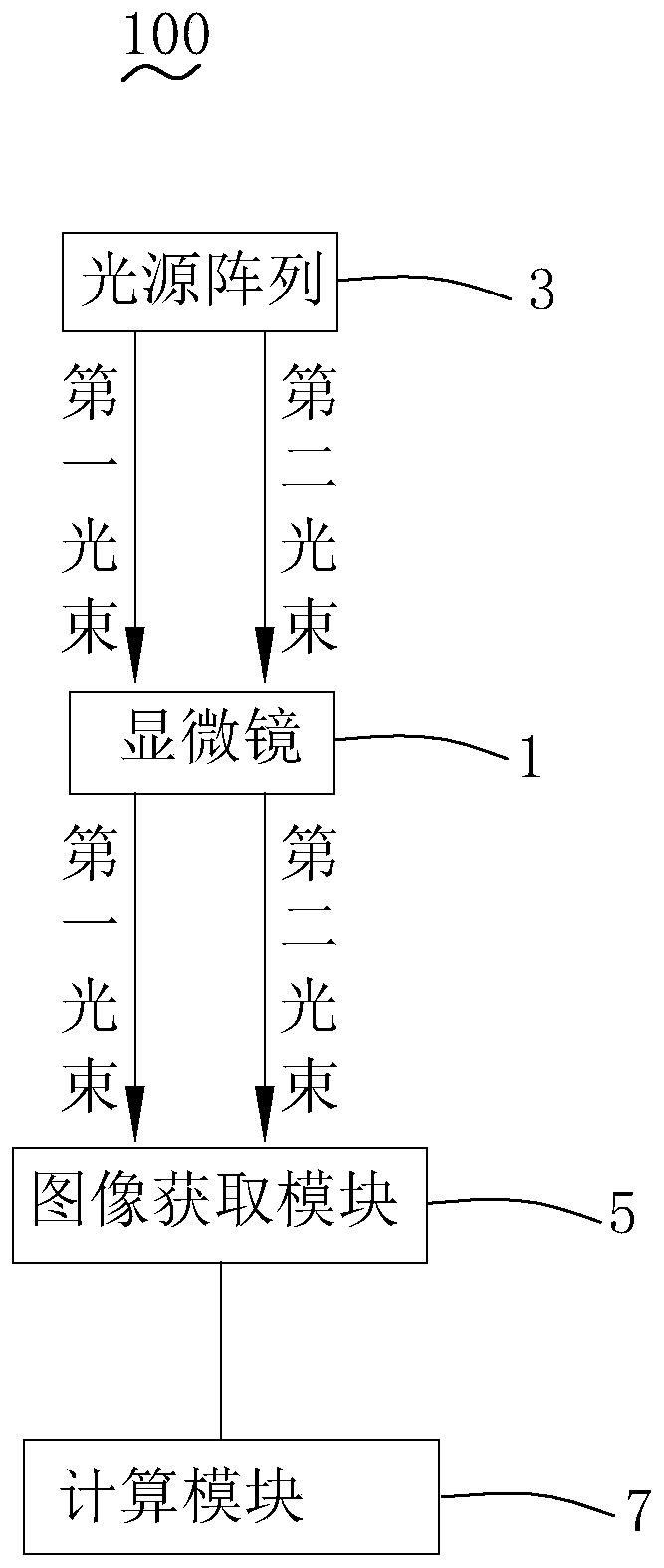
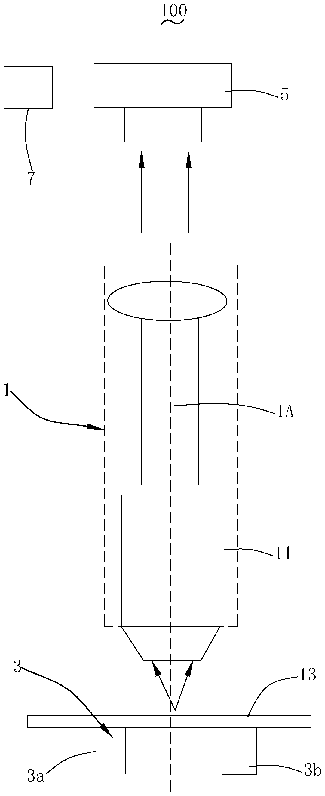
[0037] Please refer to figure 1 with figure 2 , the phase contrast microscopy imaging system 100 includes a microscope 1 with an optical axis 1A, a light source array 3 , an image acquisition module 5 and a computing module 7 .

[0038] The microscope 1 includes an objective lens 11 and a slide glass 13 . A sample (not shown in the figure) is set on the slide glass 13 and located within the field of view of the objective lens 11 .

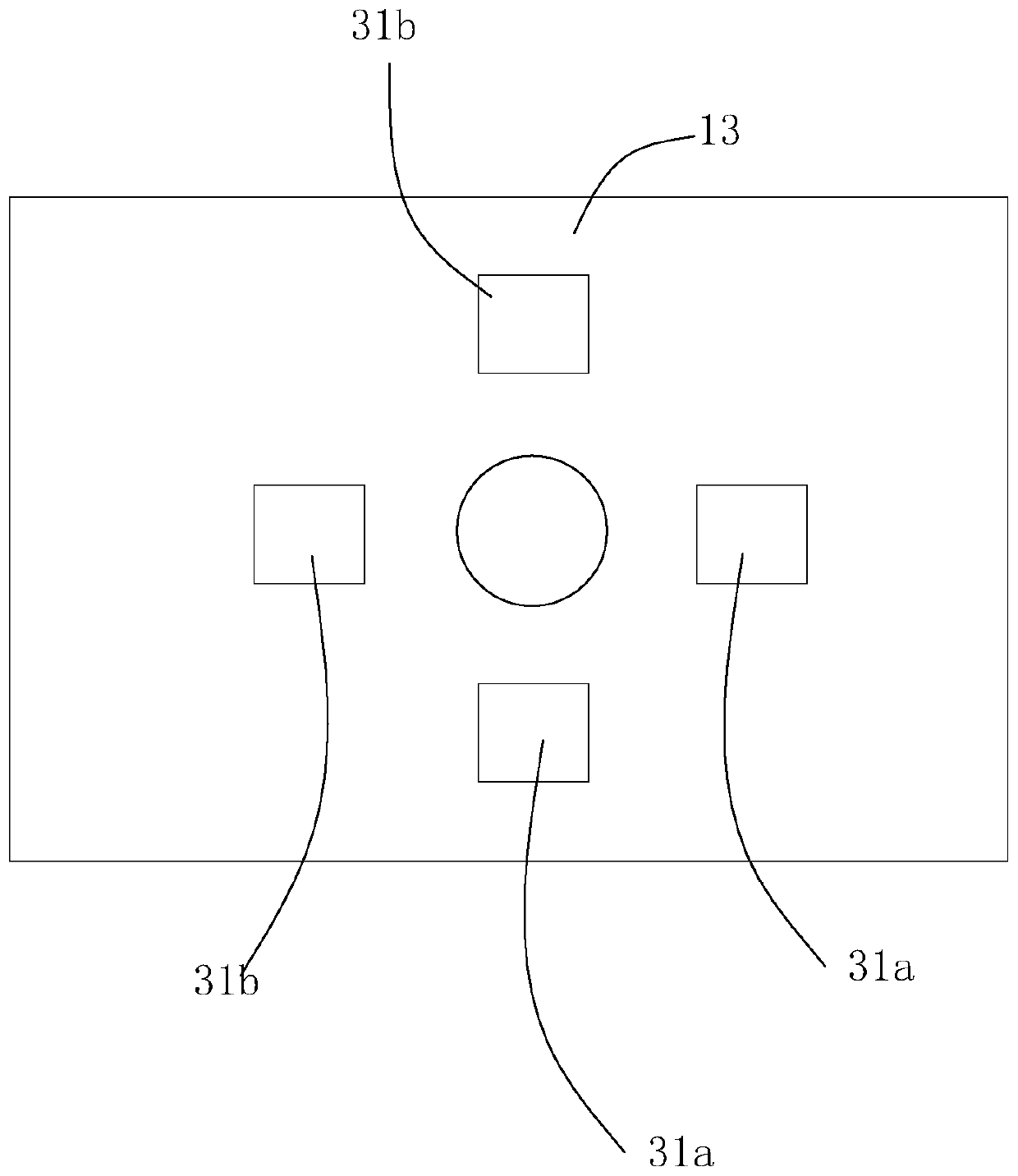
[0039] The light source array 3 is arranged on the side of the slide glass 13 away from the objective lens 11, and is used to emit a first light beam and a second light beam that are axisymmetrically arranged with respect to the optical axis 1A (that is, the first light beam and the second light beam take the optical axis 1A as the axis of symmetry). Axisymmetric arrangement), the first light beam and the second light beam pass through the sample and enter the microscope 1 from the objective lens 11. Wherein, the first light beam and the second...

Embodiment 2

[0066] The difference between the phase contrast microscopic imaging system of the second embodiment and the phase contrast microscopic imaging system of the first embodiment is that the image acquisition module 5 is a color camera. When the light source array 3 emits the first light beam, the image acquisition module 5 (color camera) takes an image (i.e. the first image) corresponding to the first light beam; when the light source array 3 emits the second light beam, the image acquisition module 5 (color camera) ) corresponding to the second light beam to take an image (ie, the second image). Wherein, the color camera can adopt a CCD camera or a CMOS camera. The photosensitive spectrum of the color camera covers the light emitting spectrum of the first light beam and the second light beam.

[0067] For a color camera, each pixel records 3 values ​​of the three color channels of R, G, and B. In this embodiment, the grayscale value I of the image and the R, G, and B values ​​...

Embodiment 3

[0076] The difference between the phase-contrast microscopic imaging system of Embodiment 3 and the phase-contrast microscopic imaging system of Embodiment 1 lies in that the spectra of the first light beam and the second light beam do not overlap. When the light source array 3 emits the first light beam, the image acquisition module 5 (monochrome camera) takes an image (i.e. the first image) corresponding to the first light beam; when the light source array 3 emits the second light beam, the image acquisition module 5 (monochrome camera) color camera) corresponding to the second light beam to take an image (that is, the second image). The photosensitive spectrum of the monochromatic camera covers the luminescent light source spectrum of the first light beam and the second light beam.

[0077] Specifically, the first light beam and the second light beam can be monochromatic light beams of different wavelengths, wherein the monochromatic light is preferably selected from the th...


PUM


Abstract

The invention provides a phase difference microscopic imaging system which is simple in structure and low in cost. The phase difference microscopic imaging system comprises a microscope with an optical axis, a light source array, an image acquisition module and a calculation module. The microscope comprises an objective lens and a glass slide, the light source array is arranged at one side, away from the objective lens, of the glass slide and is used for emitting a first light beam and a second light beam which are symmetrically arranged relative to the optical axis, and the first beam and thesecond beam penetrate a sample and enter the microscope from the objective lens, wherein the first light beam and the second light beam form a limited angle with the optical axis after penetrating through the sample, the image acquisition module is arranged at the image side of the microscope and is used for acquiring a first image corresponding to the first light beam and a second image corresponding to the second light beam, and the calculation module is used for subtracting the gray value of the first image from the gray value of the second image and normalizing the gray value of the firstimage and the gray value of the second image to a [0, 255] gray interval to obtain a phase difference image. The present invention also provides an imaging method of the phase difference microscopicimaging system which is simple and is easy to operate.

Description

【Technical field】 [0001] The invention relates to the technical field of microscopic imaging, in particular to a phase contrast microscopic imaging system and an imaging method thereof. 【Background technique】 [0002] Phase-contrast microscopy was invented by Dutch scientist Zelnick for observing unstained specimens. As the light wave passes through living cells and undyed biological specimens, its wavelength and amplitude do not change, which cannot be observed by the human eye, but its phase changes. By changing the phase difference and using light diffraction and interference phenomena, the phase contrast microscopy technique changes the phase difference into an amplitude difference to observe living cells and unstained specimens. Compared with ordinary optical microscopes and dark field microscopes, it can clearly observe living cells and certain microstructures in cells, so it is widely used in biology, medical diagnosis, scientific research, life science and other fie...

Claims


Application Information

Patent Timeline
Patent Type & Authority Applications(China)
IPC IPC(8): G02B21/36G02B21/06G02B21/34G01N21/84
CPCG02B21/365G02B21/06G02B21/34G01N21/84
Inventor 段晓东游庆虎王青青
Owner ANKON MEDICAL TECH (SHANGHAI) CO LTD
Why Eureka
Try Eureka