Fresh air system driven by external equipment

A technology of fresh air system and external equipment, applied in ventilation system, installation of electrical equipment, cleaning equipment, etc., can solve the problems of waste of financial and material resources, non-existence of connection, etc.

Active Publication Date: 2020-04-07
BEIJING SIJI MICOE SOLAR ENERGY TECH
View PDF6 Cites 2 Cited by
  • Summary
  • Abstract
  • Description
  • Claims
  • Application Information

AI Technical Summary

Problems solved by technology

[0003] However, since the fresh air fan and the vacuum cleaner belong to two different household appliances, there is no

Method used


Image

  • Fresh air system driven by external equipment
  • Fresh air system driven by external equipment
  • Fresh air system driven by external equipment

Examples


Embodiment 1

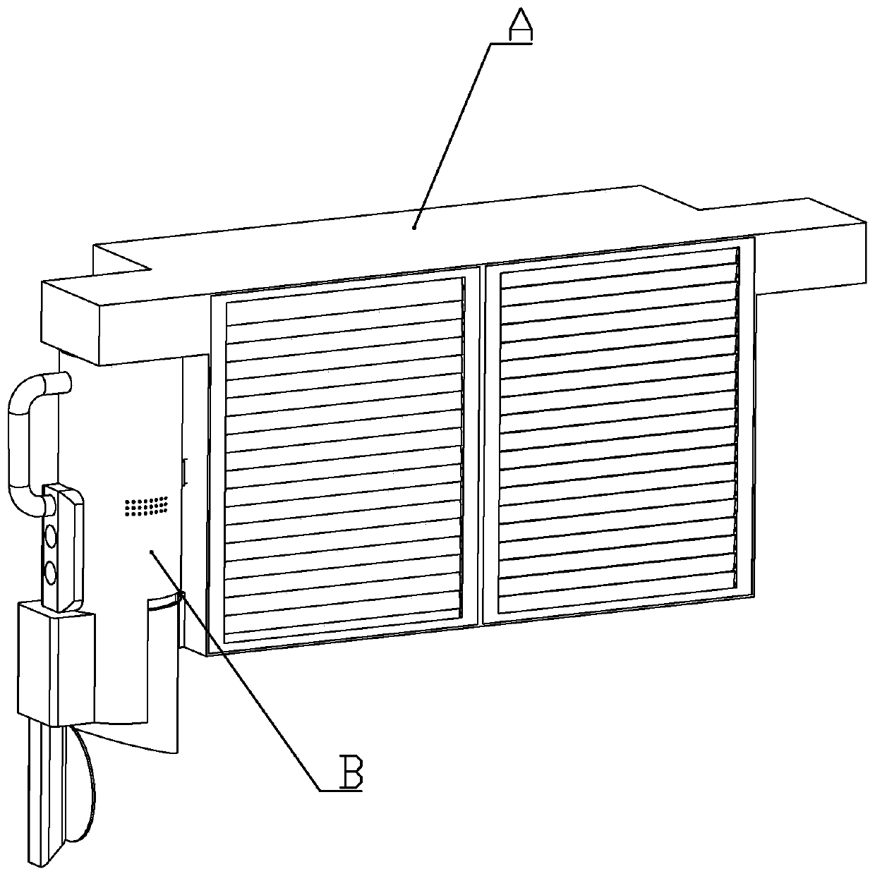
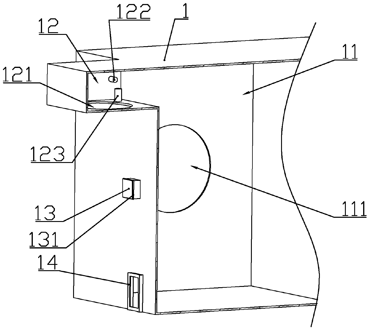
[0061] according to Figure 1 to Figure 15 As shown, a fresh air system driven by external equipment described in this embodiment includes a host A installed on the indoor wall; Ventilation fan 33 with the opposite air direction.

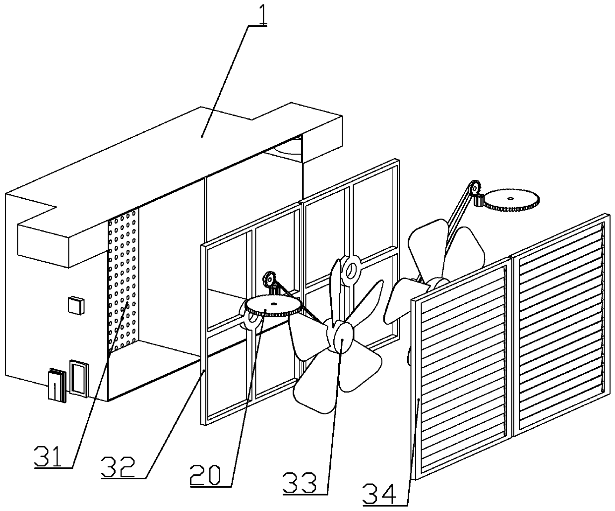
[0062] The front end of the housing is provided with two ventilation cavities 11; each of the ventilation cavities is respectively rotatably connected with a ventilation fan.

[0063] A ventilation fan frame 32 is fixedly connected in the ventilation cavity; a ventilation fan rotating sleeve is formed in the center of the ventilation fan frame; a ventilation fan connecting column 331 is formed in the center of the ventilation fan and connected to the ventilation fan rotating sleeve; Louvers 34 are fixedly connected to the front end of the cavity; ventilation holes 111 are formed on the side wall of the rear end of the ventilation cavity.

[0064] The louvers include a window frame fixedly connected to the ventilation chamber, and louvers connected...

Embodiment 2

[0131] according to Figure 16 to Figure 19 As shown, the difference between this embodiment and Embodiment 1 is that: the main machine includes a second casing 91, and two cross-flow fans 92 arranged longitudinally in the second casing; the second casing is formed with two The second ventilation cavity 911 arranged side by side; a perfusion fan is installed in each second ventilation cavity;

[0132] Shutters are installed on one side of the opening of the second ventilation cavity.

[0133] The front end of the second shell is formed with a second drive installation cavity 912 communicating with each second ventilation cavity; the bottom of the second drive installation cavity is formed with a gear plate socket; the transmission assembly C is installed in the second drive installation cavity .

[0134] The transmission assembly includes a transmission sleeve 22 slidably connected to the gear plate socket, a driven turntable 21 rotatably connected to the lower part of the t...

Embodiment 3

[0146] In this embodiment, the following improvements are made on the basis of Embodiment 1: a controller installation cavity is formed on the side wall of the vacuum cleaner housing; the controller is installed in the controller installation cavity.

[0147] A handle is formed on the side wall of the vacuum cleaner shell; a storage battery for powering the motor is arranged inside the vacuum cleaner; the storage battery is installed in the controller installation cavity or in the handle.

[0148] The side wall of the housing is located below the drive installation cavity and is fixedly connected with an electric socket; the electric socket is electrically connected with a power supply.

[0149] The side wall of the vacuum cleaner housing is fixedly connected with an electric plug that can be plugged into the electric socket; the electric plug is electrically connected to the controller; when the vacuum cleaner is suspended on the main machine, the electric plug is inserted int...


PUM


Abstract

The invention discloses a fresh air system driven by external equipment. The fresh air system comprises a main machine. The main machine comprises a shell and two ventilation fans with opposite air blowing directions. Transmission assemblies capable of driving the ventilation fan to rotate are installed at the upper ends of the left and right sides of the shell. A dust collector capable of drivingthe transmission assembly to work is detachably installed on the side wall of the shell. The dust collector comprises a dust collector shell, a draught fan slidably connected into the dust collectorshell, a dust collection box and a motor driving the draught fan to work. An output shaft of the motor is fixedly connected with a driving turntable in transmission with a transmission gear disc; a fan driving assembly for driving the fan to slide along the axis of the dust collector shell is mounted in the dust collector shell; the front end of the dust collector shell is rotationally connected with a dust collection cover capable of abutting against the open end of a dust collection box. The dust collector is hung on the outer side of the main machine, so that the motor can drive the main machine to work, and meanwhile, the dust collector can be used as a dust collection tool after being taken down.

Description

technical field [0001] The invention belongs to the technical field of home appliances, and in particular relates to a fresh air system driven by external equipment. Background technique [0002] In today's life, fresh air fans and vacuum cleaners have become common household appliances, and every household will buy them. [0003] However, since the fresh air fan and the vacuum cleaner belong to two different household appliances, there is no connection between them, and they are driven by their own internal motors, which wastes financial and material resources. Contents of the invention [0004] The technical problem to be solved by the present invention is to provide a fresh air system driven by an external device that uses a motor in a vacuum cleaner to drive a fresh air fan to work in view of the deficiencies in the prior art. [0005] In order to achieve the purpose of the present invention, the following technical solutions are adopted: a fresh air system driven by ...

Claims


Application Information

Patent Timeline
IPC IPC(8): A47L7/04A47L9/00A47L9/14A47L9/28F24F7/013
CPCA47L7/04A47L9/00A47L9/0081A47L9/1418A47L9/28F24F7/013F24F2221/18
Inventor 宋金富
Owner BEIJING SIJI MICOE SOLAR ENERGY TECH
Why Eureka
Try Eureka