
A self-lubricating bearing and its applied stone crushing device

A crushing device and stone technology, which is applied to the rigid supports of bearing components, shafts and bearings, bearing components, etc., can solve the problems of damage to the rotating shaft of the roller, low crushing efficiency, low working efficiency of the stone crusher, etc., and achieves easy rolling. , The effect of high crushing efficiency

Active Publication Date: 2022-01-11
萍乡市志和传动科技有限公司
View PDF10 Cites 0 Cited by
  • Summary
  • Abstract
  • Description
  • Claims
  • Application Information

AI Technical Summary

Problems solved by technology

And use the slots on the grinding wheel to increase the crushing force on the stone, but the spacing between the slots on the grinding wheel is relatively large, so the crushing efficiency is low; if you want to improve the crushing efficiency of the grinding wheel, you must increase the speed of the grinding wheel. The increase of the rotating speed of the grinding wheel will inevitably cause the rotating shaft of the grinding wheel to generate a large amount of heat under high-speed rotation, which will damage the rotating shaft of the grinding wheel, so it has to stop for a period of time to dissipate heat, so the crusher cannot meet the requirements of long-term work. needs
Furthermore, the crusher cannot squeeze and stir the stones, and the stones are not easy to enter the rollers for rolling, so the working efficiency of the stone crusher is low and cannot meet people's needs.
In addition, a large amount of dust is generated during the crushing process of the stone, which will cause air pollution, and the dust will be inhaled by the operating workers, endangering the health of the operating workers

Method used


Image

  • A self-lubricating bearing and its applied stone crushing device
  • A self-lubricating bearing and its applied stone crushing device
  • A self-lubricating bearing and its applied stone crushing device

Examples


Embodiment Construction

[0035] The present invention will be described in further detail below in conjunction with the accompanying drawings and specific embodiments.

[0036] see figure 1 shown;

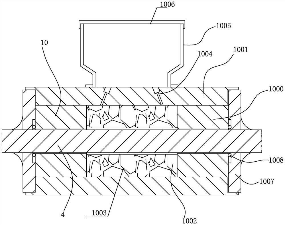
[0037] The present invention is a self-lubricating bearing, which includes a first shaft sleeve 10 and a second shaft sleeve 1000 sleeved on the rotating shaft 4, the inner walls of the first shaft sleeve 10 and the second shaft sleeve 1000 are connected to the outer side of the rotating shaft 4 Wall gap fit; the outer side of the first shaft sleeve 10 and the second shaft sleeve 1000 is provided with a base 1001, and the inner wall of the base 1001 is sealed with the outer side wall of the first shaft sleeve 10 and the second shaft sleeve 1000; An annular cavity 1002 is provided between the first bushing 10 and the second bushing 1000, and an oil storage block 1003 made of flexible microporous material is arranged inside the annular cavity 1002, and the oil storage block 1003 is 1003 is attached to the ...


PUM


Abstract

The invention discloses a self-lubricating bearing and a stone crushing device for its application. It comprises a first shaft sleeve and a second shaft sleeve sleeved on a rotating shaft. The outer side wall of the rotating shaft is clearance fit; the outer side of the first shaft sleeve and the second shaft sleeve is provided with a base, and the inner wall of the base is in sealing connection with the outer side wall of the first shaft sleeve and the second shaft sleeve; An annular cavity is provided between the first shaft sleeve and the second shaft sleeve, and an oil storage block made of flexible microporous material is arranged in the annular cavity, and the oil storage block is attached to the outer wall of the rotating shaft. Used to lubricate the outside wall of the shaft. The self-lubricating bearing can automatically lubricate the rotating shaft, reduce the friction of the rotating shaft, reduce the heat generated when the rotating shaft rotates at high speed, and avoid damage to the rotating shaft, and the stone crushing device using the self-lubricating bearing has high crushing efficiency.

Description

technical field [0001] The invention relates to the technical field of stone crushing, in particular to a self-lubricating bearing and a stone crushing device for its application. Background technique [0002] Stone is one of the indispensable materials in construction engineering, road construction, chemical industry and other fields. Stones are generally taken by quarry machines, and then crushed into a suitable size by crushing process before they can be used by people. The stone crushing process is generally that the stone is uniformly sent to the coarse crusher by the feeder for preliminary crushing, and then the produced coarse material is transported to the crusher by the belt conveyor, and the crusher is further crushed, and the finely crushed stone is sent to the crusher. The vibrating screen screens out stones of different specifications, and the stones that do not meet the particle size requirements are returned to the crusher for further crushing. [0003] The ...

Claims


Application Information

Patent Timeline
Patent Type & Authority Patents(China)
IPC IPC(8): B02C2/10B02C23/00B02C23/40F16C33/04F16C35/02B01D47/06
CPCB02C2/10B02C23/00B02C23/40F16C33/04F16C35/02B01D47/06B01D2258/02
Inventor 杜江
Owner 萍乡市志和传动科技有限公司
Learn More