Elutriator

An elutriation device and elutriation technology, applied in the field of elutriation devices, can solve problems such as short residence time, large particle size range, and no static electricity elimination design, so as to achieve low equipment failure rate and improve elutriation efficiency

Active Publication Date: 2020-04-07
WANHUA CHEM GRP CO LTD
View PDF6 Cites 0 Cited by
  • Summary
  • Abstract
  • Description
  • Claims
  • Application Information

AI Technical Summary

Problems solved by technology

[0003] The particle size range of the powder produced by friction or collision during the transportation of the particles is large, and the powder will adhere to the surface of the particles due to the static electricity generated by the friction of the particles, which is not easy to remove
For the elutriators mentioned in Chinese patents CN 1050186032 B, CN 202224355U, CN 206485999 U, and CN 201030332 Y, in the process of equipment structure design, only one-step convective separation is performed between particles and powder, the residence time is short, and no With a static elimination design, there is no mention of the removal efficiency of easily adhering powders and powders under different particle sizes
For the aforementioned problems, there is no good solution

Method used


Image

  • Elutriator
  • Elutriator
  • Elutriator

Examples


Embodiment 1-3 and comparative example 1

[0101] The particle treatment objects are: PMMA particles with an average particle size of 3mm;

[0102] The processing capacity of all elutriators used is 15t / h.

Embodiment 1

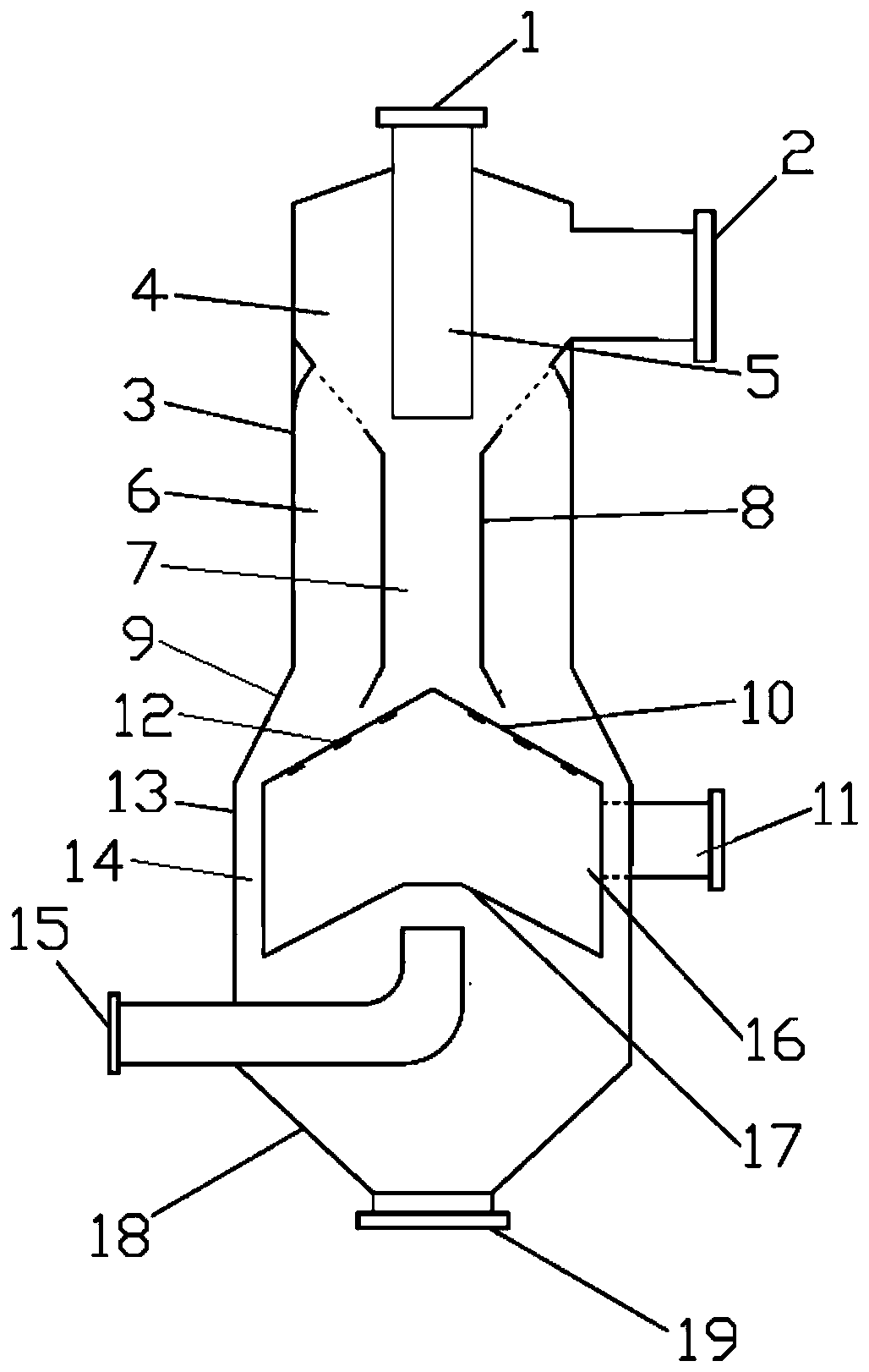
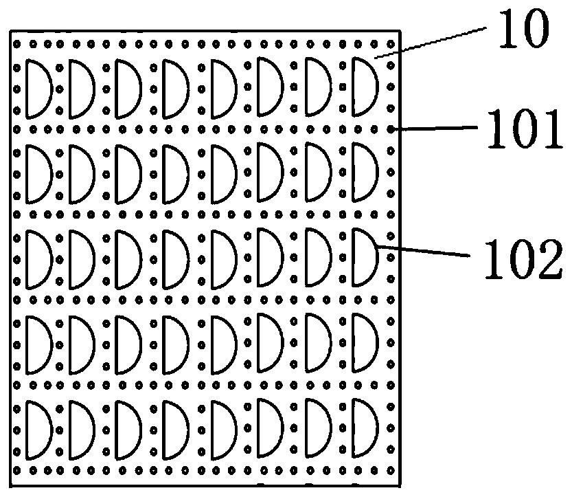
[0104] Such as Figure 1-4 As shown, the diameter of the particle inlet 1 is 200mm; the diameter of the elutriation section cylinder 3 is 700mm, and the height is 1200mm; the height of the frusto-conical cylinder 9 of the cleaning section is 175mm; the diameter of the annular channel cylinder 13 is 1000mm, and the height is 700mm, the height of the discharge cone 18 is 320mm;

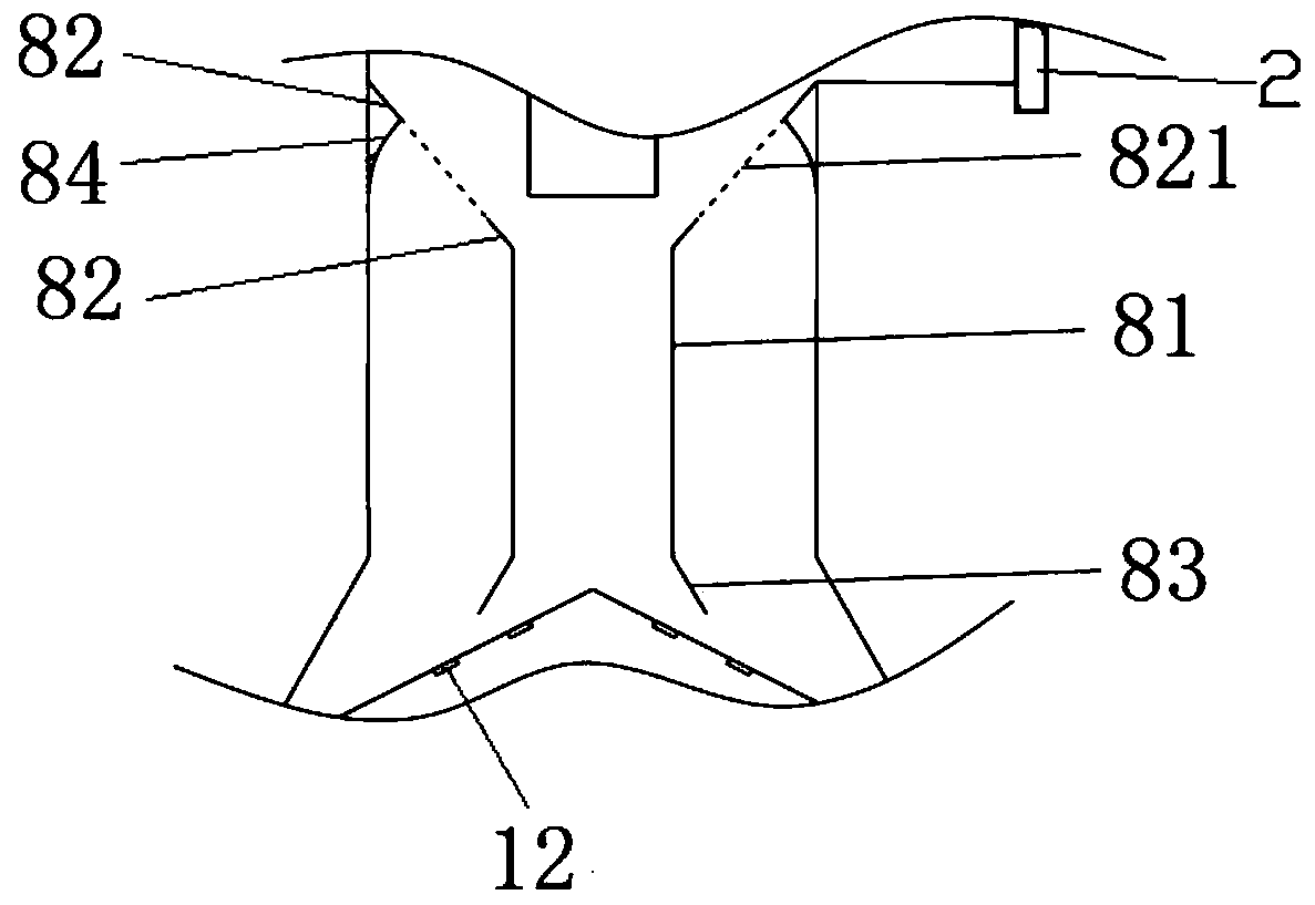
[0105] The diameter of the second enlarged diameter section 83 is 315 mm; the vertical distance H from the end edge of the second enlarged diameter section 83 to the upper surface of the cleaning plate 10 2 100mm; Elutriation passage 7 diameters are 250mm, length is 500mm; The diameter of powder gas outlet 2 is 350mm, the diameter of the first gas inlet pipe 11 is 300mm, the diameter of the second gas inlet pipe 15 is 200mm, the diameter of particle outlet 19 The diameter is 300mm;

[0106]The included angle between the cleaning plate 10 and the horizontal direction is 30°, the cone surface radius of ...

Embodiment 2

[0112] Only the following content is different from Example 1, and all the other contents and implementation process are the same as Example 1:

[0113] The diameter of the second enlarged diameter section 83 is 300 mm; the vertical distance H from the lower end edge of the second enlarged diameter section 83 to the upper surface of the cleaning plate 10 2 80mm; the elutriation channel 7 has a diameter of 250mm and a length of 550mm.


PUM


Abstract

The invention provides an elutriator. The elutriator comprises an outer cylinder, a particle inlet, a particle outlet, a particle inlet channel pipe, a flow guide inner component, a cleaning box body,a first gas inlet pipe, a second gas inlet pipe and a powder gas outlet, wherein the particle inlet and the particle outlet are formed in the top and the bottom of the outer cylinder respectively; the particle inlet channel pipe, the flow guide inner component and the cleaning box body are arranged sequentially at intervals in the outer cylinder from top to bottom; the flow guide inner componentcomprises a first diameter expanding section, a vertical section and a second diameter expanding section which are fixedly arranged in sequence from top to bottom; the cleaning box body comprises a cleaning plate, a cylindrical box wall and a gas guide plate which are sequentially fixed from top to bottom; the second gas inlet pipe penetrates through the outer cylinder, and an outlet of the secondgas inlet pipe faces upwards and is arranged under the gas guide plate; the first gas inlet pipe penetrates through the outer cylinder and is connected to the cylindrical box wall; the powder gas outlet is formed in the position, corresponding to the middle of the particle inlet channel pipe, of the outer cylinder; and the lower end diameter of the cleaning plate is greater than the upper end diameter of the first diameter expanding section, the upper end diameter of the first diameter expanding section is greater than the lower end diameter of the second diameter expanding section, the lowerend diameter of the second diameter expanding section is greater than the diameter of the vertical section, and the diameter of the vertical section is greater than or equal to the diameter of the particle inlet channel pipe.

Description

technical field [0001] The invention relates to the field of powder engineering, in particular to an elutriator. Background technique [0002] In the production process involving granular materials, in view of the physical properties of the particles themselves, especially brittle and fragile particles, in the process of pneumatic conveying and transportation, after the particles collide and rub against the wall of the device or pipe, it is easy to produce wire drawing and powder , if the powder is not removed, the particles will easily produce bubbles, spots, etc. during the later injection molding process, which will affect the product quality. In order to remove the powder in the finished granules in the industrial production process, an elutriator is often used to remove the powder before the granules enter the packaging silo. [0003] The particle size range of the powder produced by friction or collision during the transportation of particles is large. At the same tim...

Claims


Application Information

Patent Timeline
Patent Type & Authority Applications(China)
IPC IPC(8): B08B5/02B08B13/00B07B7/01B07B11/00B07B11/02B07B11/06
CPCB07B7/01B07B11/00B07B11/02B07B11/06B08B5/023B08B13/00
Inventor 石广雷郭志国黄岐善
Owner WANHUA CHEM GRP CO LTD
Why Eureka
Try Eureka