
Process for machining deep mounting hole of slewing bearing ring

A technology for slewing ring bearings and ferrules, which is applied in the technical field of processing bearing mounting holes, can solve the problems of adapter tool rod damage and scrapping, very high stability requirements, product damage and scrapping, etc., to eliminate risks and improve product quality. Stabilization and the effect of cutting amount reduction

Active Publication Date: 2020-04-07
WAFANGDIAN BEARING GRP STATE BEARING ENG TECH RES CENT CO LTD
View PDF8 Cites 0 Cited by
  • Summary
  • Abstract
  • Description
  • Claims
  • Application Information

AI Technical Summary

Problems solved by technology

[0002] In recent years, with the rapid development of wind power technology, wind turbines are increasingly developing towards large megawatts and offshore wind turbines, and the geometric dimensions of the products are constantly increasing. Along with the increase and deepening of the bolt hole size, the mechanical properties of materials are improved. , the difficulty of machining has also increased exponentially. The requirements for the tool and the accuracy of the equipment have put forward higher requirements. In the case of tool damage or product injury and scrapping, this article introduces a rotary The deep hole processing method of support products aims to reduce processing costs and eliminate processing risks on the basis of ensuring product quality, and has extensive practical value
[0003] Taking the processing of φ45 mounting hole as an example, the original processing method needs to drill directly from one side with a flexible drill rod with a length of 6-8 times the diameter and a diameter of . Because it is high-speed drilling, the linear speed during processing is close to 150m / min , so this processing method has very high requirements on the stability of the tool and equipment and the material to be processed. Any fluctuations that may occur may lead to damage to the tip of the tool, the adapter or even the tool bar and the scrapping of the product, resulting in manufacturing The sharp rise in cost, so in order to accommodate some abnormal factors in processing

Method used


Image

  • Process for machining deep mounting hole of slewing bearing ring
  • Process for machining deep mounting hole of slewing bearing ring
  • Process for machining deep mounting hole of slewing bearing ring

Examples


Embodiment 1

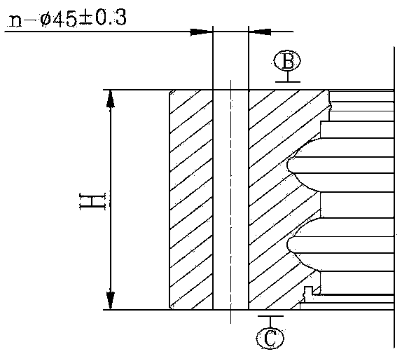
[0022] A process for processing the installation deep hole of the slewing ring bearing ring, which is used to process the installation hole with a diameter of φ45 in the finished product, and the steps include, as figure 1 As shown, the first hole is processed as a through hole, and the processing method of the first hole is to use a flexible drill that meets the requirements to drill directly from the B surface at one time. All dimensions in the drawings are in mm.

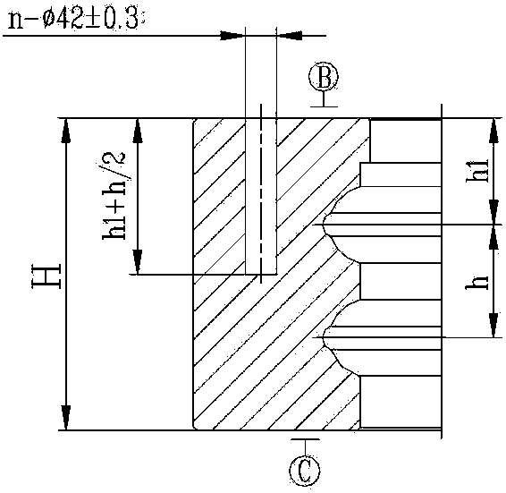
[0023] Such as figure 2 As shown, the remaining holes are first processed with a φ42mm U-drill, the processing depth is h2, the height of the slewing ring bearing is H, H>h2, and the processing depth h2 is about half of the end face height.

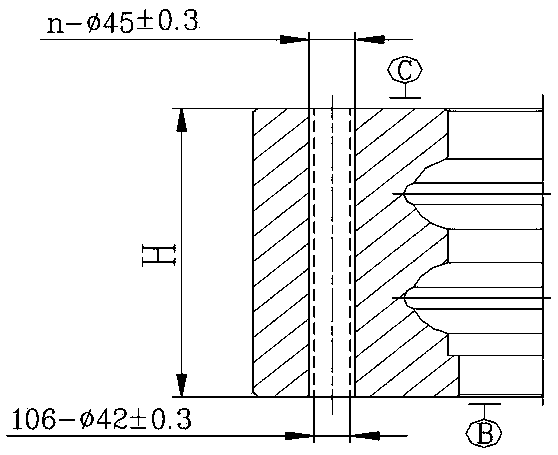
[0024] Such as image 3 As shown, after processing, turn the material and align it with the specified benchmark, then align it with the first hole, determine the zero point position (the starting position of processing, the angle is 0° at this time), and then use a φ42mm ...


PUM


Abstract

The invention belongs to the technical field of process for machining bearing mounting holes, is applied to the field of deep hole machining of slewing bearing products, and particularly relates to aprocess for machining a deep mounting hole of a slewing bearing ring. The process comprises the following steps: machining a first hole into a through hole and machining other holes by using a U drill, wherein the machining depth is h2, the height of the slewing bearing is H, H>h2, other holes are turned over and aligned after being drilled for the first time, then the holes are drilled through the U-shaped drill, chambering machining is conducted through a flexible drill, and finally the size required by a finished product is achieved. The stability of the machining process and the stabilityof the product quality can be guaranteed.

Description

technical field [0001] The invention belongs to the technical field of processing bearing mounting holes, is applied to the field of deep hole processing of slewing bearing products, and specifically relates to a process for processing deep holes for mounting rings of slewing bearing bearings. Background technique [0002] In recent years, with the rapid development of wind power technology, wind turbines are increasingly developing towards large megawatts and offshore wind turbines, and the geometric dimensions of the products are constantly increasing. Along with the increase and deepening of the bolt hole size, the mechanical properties of materials are improved. , the difficulty of machining has also increased exponentially. The requirements for the tool and the accuracy of the equipment have put forward higher requirements. In the case of tool damage or product injury and scrapping, this article introduces a rotary The deep hole processing method for supporting products...

Claims


Application Information

Patent Timeline
IPC IPC(8): B23B35/00
CPCB23B35/00
Inventor 郑晓菲赵铭徐猛徐向超刘艳芳李强张雅娜杨金雷
Owner WAFANGDIAN BEARING GRP STATE BEARING ENG TECH RES CENT CO LTD
Features
  • Generate Ideas
  • Intellectual Property
  • Life Sciences
  • Materials
  • Tech Scout
  • Unparalleled Data Quality
  • Higher Quality Content
  • 60% Fewer Hallucinations
Learn More