Cast-in-place pile leaking stoppage hole reinforcing method and structure

A cast-in-place pile and leak hole technology, applied in the field of geotechnical engineering, can solve the problems of time-consuming and laborious, can not ensure whether there will be problems in the cast-in-place pile, and achieve the effects of reducing rework, reasonable design of construction steps, and simple operation.

Pending Publication Date: 2020-04-07
CCCC FOURTH HARBOR ENG CO LTD
View PDF0 Cites 2 Cited by
  • Summary
  • Abstract
  • Description
  • Claims
  • Application Information

AI Technical Summary

Problems solved by technology

The general post-processing method is often time-consuming and labor-intensive, and it cannot ensure whether there will be problems in the subsequent construction of cast-in-situ piles

Method used


Image

  • Cast-in-place pile leaking stoppage hole reinforcing method and structure
  • Cast-in-place pile leaking stoppage hole reinforcing method and structure
  • Cast-in-place pile leaking stoppage hole reinforcing method and structure

Examples


Embodiment Construction

[0026] The following will clearly and completely describe the technical solutions in the embodiments of the present invention with reference to the accompanying drawings in the embodiments of the present invention. Obviously, the described embodiments are only part of the embodiments of the present invention, not all of them. Based on the embodiments of the present invention, all other embodiments obtained by persons of ordinary skill in the art without creative efforts fall within the protection scope of the present invention.

[0027] It should be noted that all directional indications (such as up, down, left, right, front, back...) in the embodiments of the present invention are only used to explain the relationship between the components in a certain posture (as shown in the accompanying drawings). Relative positional relationship, movement conditions, etc., if the specific posture changes, the directional indication will also change accordingly.

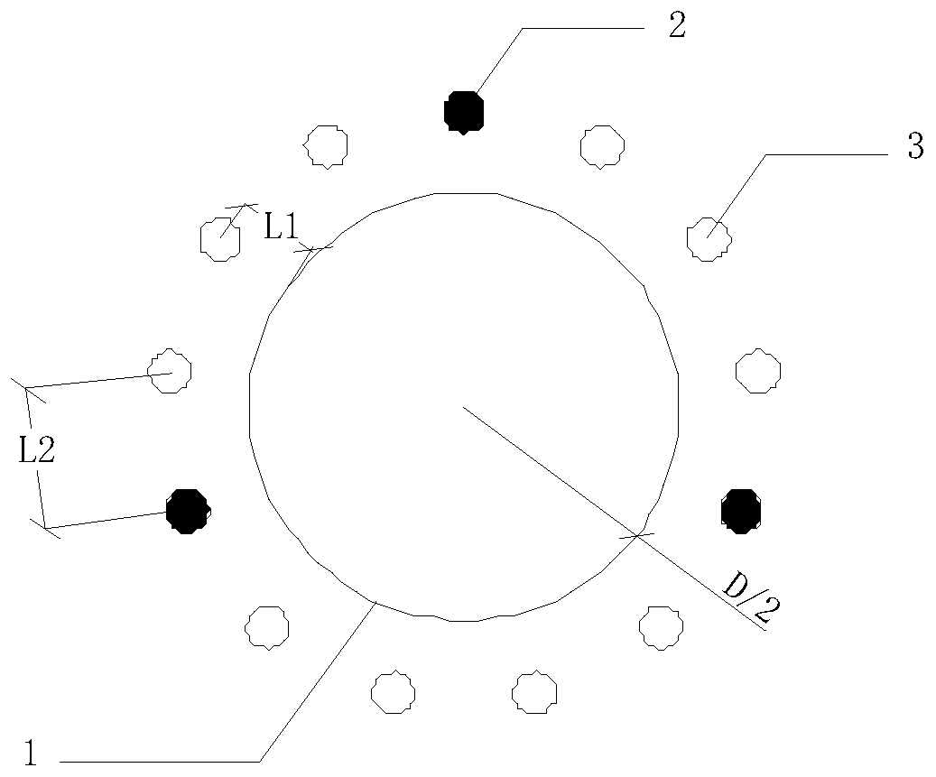
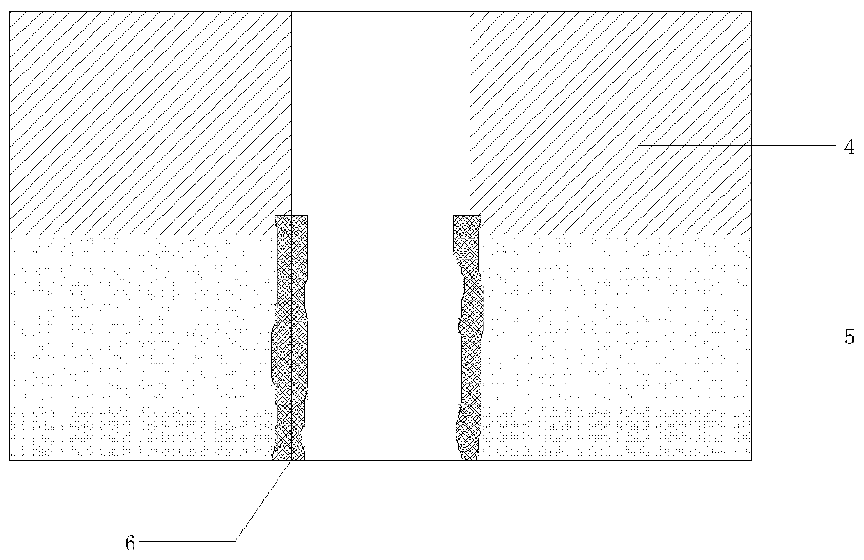
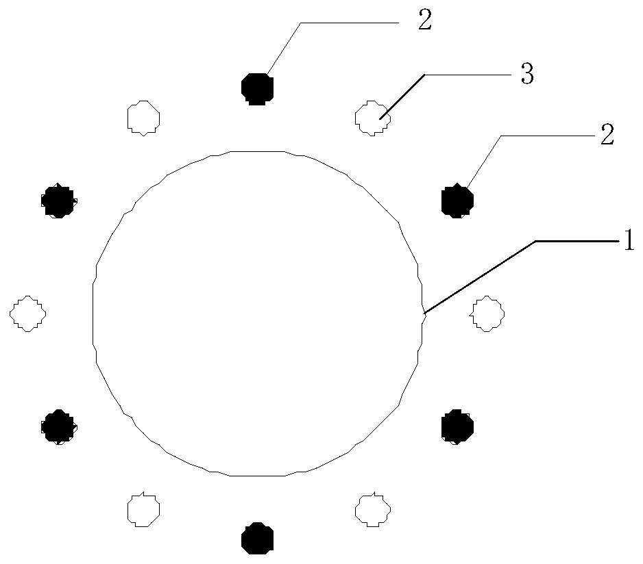
[0028] Such as figure 1...


PUM


Abstract

The invention discloses a cast-in-place pile leaking stoppage hole reinforcing method and structure. Before a cast-in-place pile is constructed, a grouting influence radius test is carried out, a slurry influence radius is detected, a leaking stoppage hole and a wall reinforcing hole are formed around a cast-in-place pile hole, slurry is injected into the leaking stoppage hole and the wall reinforcing hole, after the slurry is solidified, construction of the cast-in-place pile is carried out, and an easily-leaking easily-collapsing layer around the cast-in-place pile can be reinforced. The method and structure are suitable for construction of the cast-in-place pile of the easily-leaking easily-collapsing layer such as gravel, cobble and limestone, the construction steps are reasonable in design, operation is easy, quality problems of slurry leaking, hole collapsing and the like in the construction process of the cast-in-place pile can be effectively solved, continuity and smoothness ofthe construction of the cast-in-place pile can be ensured, the construction efficiency of the cast-in-place pile can be improved, rework due to quality problems in the hole forming construction process of the cast-in-place pile can be reduced, and the construction quality of the cast-in-place pile can be effectively ensured.

Description

technical field [0001] The invention relates to the technical field of geotechnical engineering, in particular to a method and structure for plugging and fixing holes of cast-in-situ piles. Background technique [0002] At present, with the development of economy and society, there are more and more highway and bridge construction projects. As a mature and reliable foundation form, cast-in-place piles are widely used in highway and bridge engineering. However, under complex geological conditions, especially in sandy, pebble and other highly permeable strata or limestone strata, there are often construction problems such as slurry leakage and hole collapse, which increase non-production time and affect construction efficiency. After construction problems such as slurry leakage and hole collapse occur, it is generally necessary to suspend the construction. Depending on the situation of slurry leakage and hole collapse, the construction equipment will be withdrawn, and measures...

Claims


Application Information

Patent Timeline
Patent Type & Authority Applications(China)
IPC IPC(8): E02D5/36E02D3/12
CPCE02D3/12E02D5/36
Inventor 黄宇胡永光刘深农伟明周小林曾念李成勇程一夫唐友鑫黄海涛
Owner CCCC FOURTH HARBOR ENG CO LTD
Why Eureka
Try Eureka