
DC contactor

A DC contactor and electrical contact technology, applied in the direction of relays, electromagnetic relays, electromagnetic relay details, etc., can solve problems such as unstable contact, large air pressure resistance, and stagnation, and achieve the effect of improving contact reliability

Inactive Publication Date: 2020-04-07
中泰福安(东莞)电子科技有限公司
View PDF7 Cites 0 Cited by
  • Summary
  • Abstract
  • Description
  • Claims
  • Application Information

AI Technical Summary

Problems solved by technology

The operation of the transmission part mainly depends on the traction and guidance of the moving iron core in the magnetic circuit system, and then the connection and breaking of the contact part is operated by the transmission of the metal push rod. Due to the high life requirements of the product, the moving iron core in the magnetic circuit system The operating action of the moving bridge and the reliability of the operating action of the moving bridge plate are very high, so the moving iron core may have a large air pressure resistance during operation, resulting in large power consumption, and the rotation of the bridge plate during operation leads to unstable contact. It will affect the contact reliability between the contacts, and in extreme cases, there will be stagnation, which will affect the working reliability and normal working life of the product
The arc extinguishing effect of nitrogen or inert gas is still not ideal, and the product life is not significantly improved. The existing DC contactors in the industry have the disadvantages of high power consumption, low working reliability, and weak arc extinguishing ability. Therefore, , it is not ideal from the point of view of economy and practicality

Method used


Image

  • DC contactor
  • DC contactor
  • DC contactor

Examples


Embodiment Construction

[0028] The present invention is further described in conjunction with the following examples.

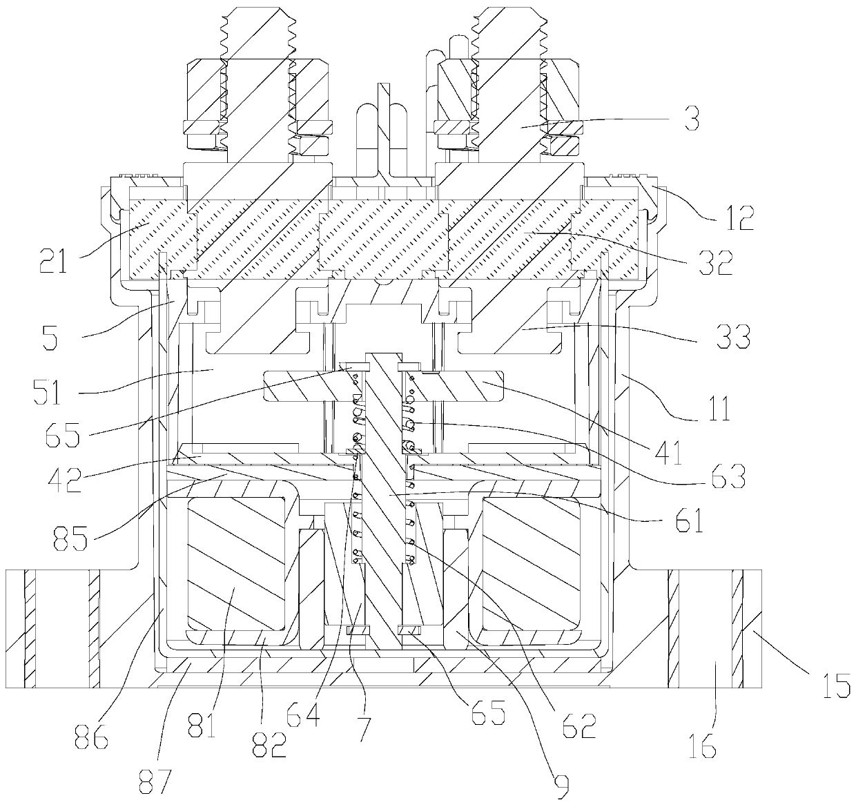
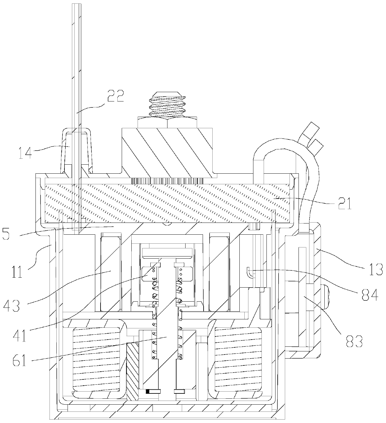
[0029] Depend on Figure 1 to Figure 7 It can be seen that a DC contactor described in this embodiment includes an insulating shell, a sealing member, an electrical contact member, a mechanical transmission member, and an electromagnetic drive member. Cover 12, a side cover 13 arranged on the side of the casing 11, and a notch shield 14 arranged on the top of the upper cover 12;

[0030] The sealing member includes glue 21 and an exhaust copper pipe 22 arranged on the scissor shield 14;

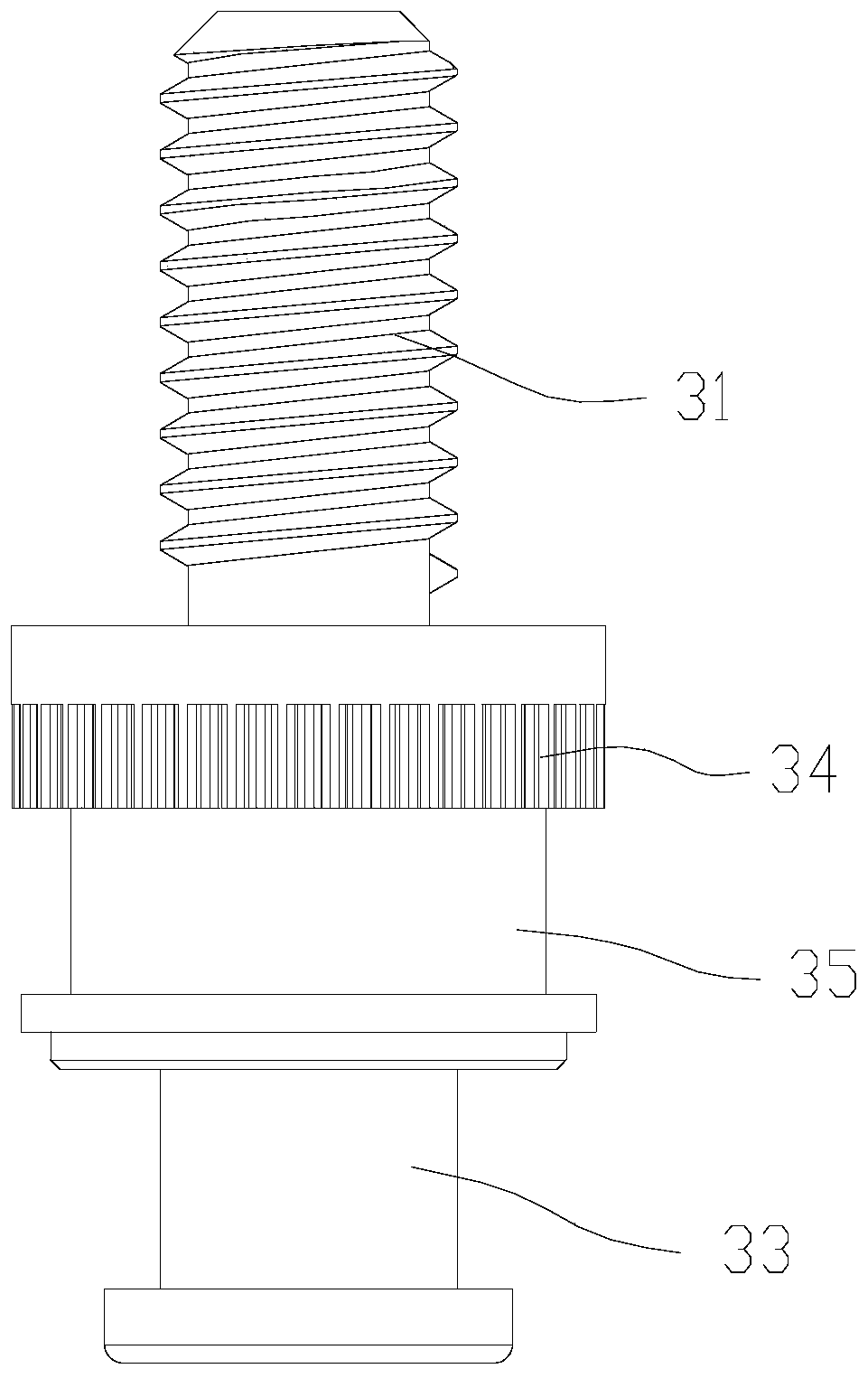
[0031] The electrical contact member includes a static contact 3, a moving bridge plate 41, an insulating cover 5, an insulating plate 42 and a magnet 43; the insulating cover 5 and the insulating plate 42 are all arranged in the housing 11; the insulating cover 5 and the An insulating cavity 51 is formed between the insulating plates 42; the static contact 3 protrudes into the insulating cavity ...


PUM


Abstract

The invention relates to the technical field of contactors, in particular to a DC contactor. The DC contactor comprises an insulating shell, a sealing component, an electrical contact component, a mechanical transmission component and an electromagnetic driving component; the insulating shell comprises a shell, an upper cover arranged at the top of the shell, a side cover plate arranged on the side surface of the shell and a shearing protective cover arranged at the top of the upper cover; and a guide positioning column for guiding and positioning the movable bridge plate is arranged in the insulating cover. Through the arrangement of a gasket, an over-travel spring and a limiting clamp spring, the action of the movable bridge plate and the contact pressure of the movable bridge plate andthe static contact are ensured; through the arrangement of the guide positioning column, the reciprocating motion of the movable bridge plate can be matched, the shaft rotation range in the movement of the movable bridge plate is limited, and the contact reliability of the movable bridge plate and the static contact is ensured to be improved.

Description

technical field [0001] The invention relates to the technical field of contactors, in particular to a DC contactor. Background technique [0002] The DC contactor in the prior art is mainly composed of a magnetic circuit part, a transmission part and a contact part, and the inside of the product is filled with nitrogen or a mixed inert gas to extinguish the arc to ensure the product life. The operation of the transmission part mainly depends on the traction and guidance of the moving iron core in the magnetic circuit system, and then the connection and breaking of the contact part is operated by the transmission of the metal push rod. Due to the high life requirements of the product, the moving iron core in the magnetic circuit system The operating action of the moving bridge and the reliability of the operating action of the moving bridge plate are very high, so the moving iron core may have a large air pressure resistance during operation, resulting in large power consumpt...

Claims


Application Information

Patent Timeline
IPC IPC(8): H01H50/54H01H50/56H01H50/02H01H50/16
CPCH01H50/023H01H50/16H01H50/546H01H50/56
Inventor 徐灿汤保成袁进
Owner 中泰福安(东莞)电子科技有限公司
Features
  • Generate Ideas
  • Intellectual Property
  • Life Sciences
  • Materials
  • Tech Scout
  • Unparalleled Data Quality
  • Higher Quality Content
  • 60% Fewer Hallucinations
Learn More