Eureka AIR delivers breakthrough ideas for toughest innovation challenges, trusted by R&D personnel around the world.

Centrifugal centripetal flow beam tube type water bed reactor

A bundle tube and reactor technology, applied in the direction of chemical methods, chemical instruments and methods, chemical/physical processes, etc. that make gas medium react with gas medium, can solve the problems of increased power consumption, short residence time, and low reaction efficiency and other problems, to achieve the effect of reducing power consumption, reducing the number of cycles, and prolonging the residence time

Pending Publication Date: 2020-04-10
NANJING JUTUO CHEM TECH
View PDF0 Cites 4 Cited by
  • Summary
  • Abstract
  • Description
  • Claims
  • Application Information

AI Technical Summary

Problems solved by technology

[0002] The radial beam tube reactor is a commonly used chemical reactor. At present, when the radial beam tube reactor is working, the reaction gas generally flows radially from the inside to the outside or from the outside to the inside. Because the reactor generally Both are slender structures, so that the residence time of the reaction gas in the reactor is short, and the single-pass reaction efficiency is low, so that most of the reaction raw materials need to be recycled many times, which increases the power consumption of the reaction

Method used


Image

  • Centrifugal centripetal flow beam tube type water bed reactor
  • Centrifugal centripetal flow beam tube type water bed reactor
  • Centrifugal centripetal flow beam tube type water bed reactor

Examples


Embodiment Construction

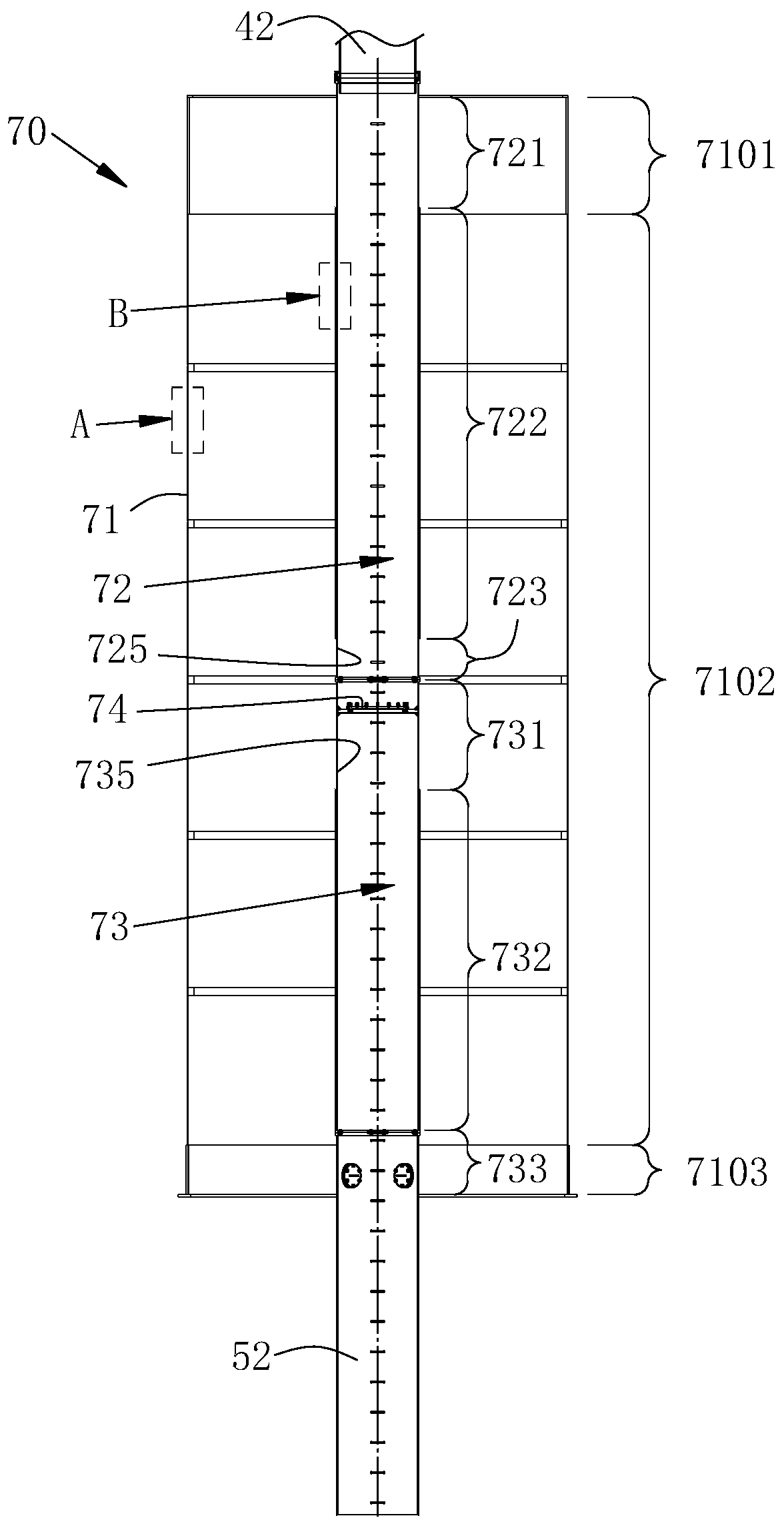
[0041] see figure 1 , a centrifugal centripetal flow beam tubular water bed reactor, which includes a shell 10, the shell 10 includes a cylindrical shell 11, an upper head 12 installed on the upper end of the shell 11 and an upper head 12 installed on the shell The lower head 13 of the lower end of 11. Inside the housing a radial distributor 70 is arranged.

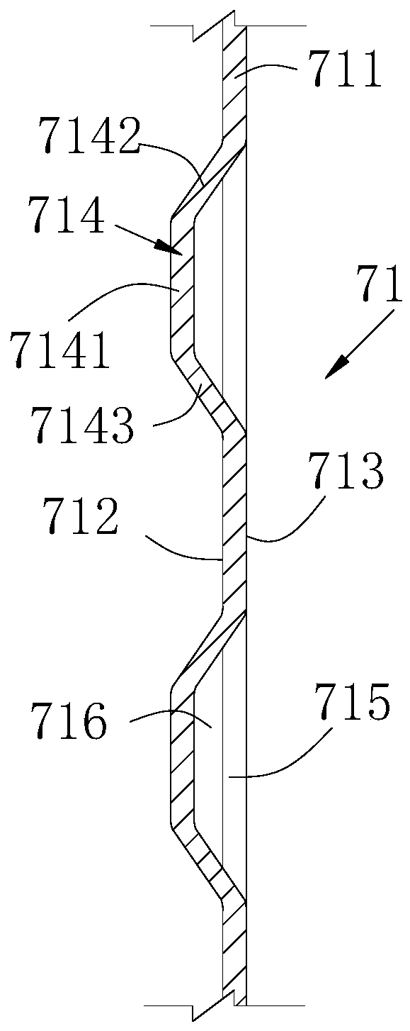
[0042] Please also see figure 2 The radial distributor 70 includes an inner radial basket 79 and an outer radial basket 71 sleeved on the outside of the inner radial basket. There is an annular gap 75 between the outer radial frame 71 and the cylinder 11, and the catalyst cover plate 14 is installed on the top of the inner radial basket 79 and the outer radial basket 71, and the catalyst support plate 15 is installed on the bottom of the inner radial basket 79 and the outer radial basket 71; the inner radial basket, outer radial basket, catalyst cover plate and catalyst The space between the support plates is formed a...


PUM


Abstract

The invention discloses a centrifugal centripetal flow beam tube type water bed reactor which comprises a shell, and a radial distributor comprising an inner radial basket diameter and an outer radialbasket diameter is arranged in the shell. An annular gap is formed between an outer radial basket and a cylinder body, a reaction area is formed between an inner radial basket and the outer radial basket, and the inner radial basket comprises a gas inlet part and a gas outlet part which are connected up and down. A first airflow channel is arranged on the air inlet part. A second airflow channelis arranged on the gas outlet part. A third airflow channel is arranged on the outer radial basket. The reaction area is divided into an upper reaction area and a lower reaction area. A first reactiongas enters the upper reaction area through the gas inlet part for reaction to form a partial reaction gas, and then the partial reaction gas enters the annular gap. A second reaction gas enters the annular gap through a side reaction gas inlet pipe and is mixed with the partial reaction gas to form mixed reaction gas, and the mixed reaction gas enters the lower reaction area for reaction. By utilizing the reactor, the retention time of reaction gas in the reactor can be effectively prolonged, so that the one-way reaction efficiency is improved.

Description

technical field [0001] The invention belongs to chemical synthesis reactors, in particular to a centrifugal centripetal flow beam tubular water bed reactor. Background technique [0002] The radial beam tube reactor is a commonly used chemical reactor. At present, when the radial beam tube reactor is working, the reaction gas generally flows radially from the inside to the outside or from the outside to the inside. Because the reactor generally Both are slender structures, so that the residence time of the reaction gas in the reactor is short, and the single-pass reaction efficiency is low, so that most of the reaction raw materials need to be recycled many times, which increases the power consumption of the reaction. Contents of the invention [0003] In order to solve the above problems, the present invention proposes a reactor, which can effectively increase the residence time of the reaction gas in the reactor to improve the single-pass reaction efficiency. The specifi...

Claims


Application Information

Patent Timeline
IPC IPC(8): B01J8/06B01J12/00
CPCB01J8/06B01J12/00B01J2208/00557
Inventor 卢健王雪林
Owner NANJING JUTUO CHEM TECH
Why Eureka
Eureka Blog
Learn More