
Raw material grinding device for magnet production

A technology of grinding device and raw materials, applied in the field of magnet production, can solve the problems of complex manufacturing structure, slow grinding speed and long time, and achieve the effects of simple structure, strong practicability and portable operation

Inactive Publication Date: 2020-04-10
安徽天宇磁业有限公司
View PDF11 Cites 5 Cited by
  • Summary
  • Abstract
  • Description
  • Claims
  • Application Information

AI Technical Summary

Problems solved by technology

[0004] The purpose of the present invention is to solve the disadvantages of complex manufacturing structure and high production cost of the grinding machinery in the prior art, and at the same time, when grinding the raw materials of the magnet, the grinding speed is slow and the time is long, which undoubtedly affects the production efficiency of the magnet. , and proposed a raw material grinding device for magnet production

Method used


Image

  • Raw material grinding device for magnet production
  • Raw material grinding device for magnet production
  • Raw material grinding device for magnet production

Examples


Embodiment 1

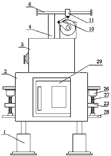
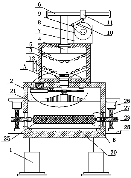
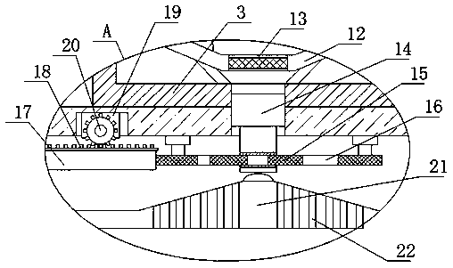
[0027] refer to Figure 1-6 , a raw material grinding device for magnet production, comprising two symmetrically arranged support bases 1, the same grinding box 2 is fixedly installed on the top of the two support bases 1, a crushing box 3 is fixedly installed on the top of the grinding box 2, and the crushing box The top of 3 is slidably connected to the pressing rod 4, the bottom of the pressing rod 4 extends into the crushing box 3 and the crushing block 5 is fixedly installed, and the top of the pressing rod 4 extends to the top of the crushing box 3 and is fixedly installed with a cross bar 6. The drive assembly is fixedly installed on the cross bar 6, the partition plate 12 is fixedly installed in the crushing box 3, and a through hole is opened in the middle position of the partition plate 12, and a matching screen 13 is fixedly installed in the through hole, The crushing box 3 and the grinding box 2 are provided with connected connecting holes, and a feeding pipe 14 is...

Embodiment 2

[0036] A raw material grinding device for magnet production, comprising two symmetrically arranged support bases 1, the same grinding box 2 is fixedly installed on the top of the two support bases 1, a crushing box 3 is fixedly installed on the top of the grinding box 2, and the crushing box 3 The top of the push rod 4 is slidingly connected with the pressing rod 4, the bottom of the pressing rod 4 extends into the crushing box 3 and the crushing block 5 is fixedly installed, and the top of the pressing rod 4 extends above the crushing box 3 and the cross bar 6 is fixedly installed , the drive assembly is fixedly installed on the cross bar 6, and the drive assembly will drive the crushing block 5 to reciprocate longitudinally, so the magnet raw material in the crushing box 2 can be crushed by using the crushing block 5, and a partition 12 is fixedly installed in the crushing box 3 , a through hole is provided at the middle position on the partition plate 12, and a matching scre...


PUM


Abstract

The invention belongs to the technical field of magnet production, and particularly relates to a raw material grinding device for magnet production. The following scheme is provided for solving the problems that an existing grinding machine is complex in manufacturing structure and high in production cost, and meanwhile, when raw materials of magnets are ground, the grinding speed is low, the timeis long, and the production efficiency of the magnets is affected undoubtedly. According to the scheme, the raw material grinding device comprises two supporting bases which are symmetrically arranged, wherein the same grinding box is fixedly mounted on the tops of the two supporting bases; a crushing box is fixedly mounted on the top of the grinding box; a pressing rod is connected to the top ofthe crushing box in a sliding mode; and the bottom of the pressing rod extends into the crushing box and is fixedly equipped with a crushing block. The raw material grinding device is simple in structure, the raw materials of the magnets can be crushed through the crushing box, and after crushing, materials in a grinding groove are ground through a grinding rod; the grinding fineness of the materials can be controlled by adjusting the height of the grinding rod; operation is convenient; and high practicability is achieved.

Description

technical field [0001] The invention relates to the technical field of magnet production, in particular to a raw material grinding device for magnet production. Background technique [0002] The composition of the magnet is iron, cobalt, nickel and other atoms. The internal structure of the atom is relatively special, and it has a magnetic moment itself. Magnets can generate magnetic fields and have the characteristics of attracting ferromagnetic substances such as iron, nickel, cobalt and other metals. The manufacturing process of magnets is: ingredients-melting-grinding-pressing-sintering (sintered NdFeB has)- -Processing-Magnetizing to make finished products, the processing process includes: grinding, slicing, wire cutting, drilling, trepanning, electroplating and so on. [0003] The existing grinding machinery has complex manufacturing structure and high production cost. At the same time, when grinding the raw materials of magnets, the grinding speed is slow and the tim...

Claims


Application Information

Patent Timeline
IPC IPC(8): B02C21/00B02C1/14B02C4/10B02C4/44B02C4/34B02C4/28
CPCB02C1/14B02C4/10B02C4/286B02C4/34B02C4/44B02C21/00
Inventor 岳武卫薛海全
Owner 安徽天宇磁业有限公司
Learn More