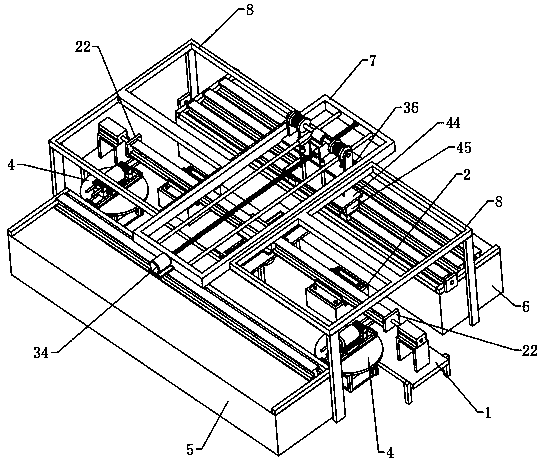
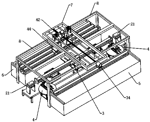
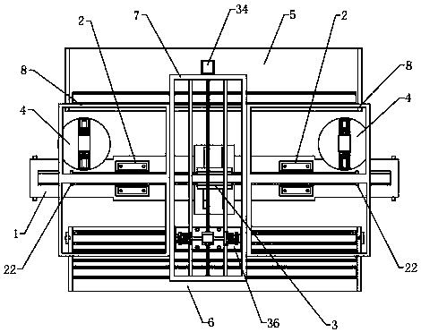
Steel rail kidney hole machining device used for rail traffic

A processing device and rail transit technology, applied in the field of rail transit, can solve the problems of high precision requirements, reduced processing efficiency, time-consuming and labor-intensive manual operations, etc.

Active Publication Date: 2020-04-10
FUSHIKOU RAILWAY EQUIP ZHEJIANG CO LTD
View PDF10 Cites 10 Cited by
  • Summary
  • Abstract
  • Description
  • Claims
  • Application Information

AI Technical Summary

Problems solved by technology

[0002] Railway track, the full name of railway track, is a kind of railway facility, used on the railway, and cooperates with the switch and the switch, so that the train can walk without turning. The track is usually composed of two balanced steel rails, and the rails are fixed on the sleepers. , under the sleeper is ballast. For the rail waist hole, the traditional processing method is to put the rail head upright, and drill the rail waist hole horizontally through the spindle of the horizontal machine tool or the right-angle head of the vertical machine tool, which requires high precision. , the existing equipment cannot realize automatic loading and unloading, and it is difficult to accurately position the rail during processing, which is easy to cause slight shaking of the rail during processing, and manual adjustment is required. Manual operation is time-consuming and laborious, reducing processing efficiency. Therefore, we have proposed a kind of rail waist hole processing device for rail transit, in order to solve the above-mentioned problems

Method used


Image

  • Steel rail kidney hole machining device used for rail traffic
  • Steel rail kidney hole machining device used for rail traffic
  • Steel rail kidney hole machining device used for rail traffic

Examples


Embodiment Construction

[0025] In order to make the object, technical solution and advantages of the present invention clearer, the present invention will be further described in detail below in conjunction with the accompanying drawings and embodiments. It should be understood that the specific embodiments described here are only used to explain the present invention, not to limit the present invention.

[0026] In the description of the present invention, it should be noted that the terms "center", "upper", "lower", "left", "right", "front", "rear", "vertical", "horizontal", The orientation or positional relationship indicated by "inner", "outer", etc. is based on the orientation or positional relationship shown in the drawings, and is only for the convenience of describing the present invention and simplifying the description, rather than indicating or implying that the referred device or element must have Certain orientations, constructed and operative in certain orientations, therefore are not t...


PUM


Abstract

The invention relates to the technical field of rail traffic, in particular to a steel rail kidney hole machining device used for rail traffic. The steel rail kidney hole machining device comprises amachining table. A carrying table is arranged on the top of the machining table. End portion positioning assemblies are arranged at the two ends of the machining table correspondingly. A side portionpositioning assembly is arranged below the carrying table. The side portion positioning assembly comprises two side portion clamping blocks, and rotating tables are arranged on one sides of the two ends of the machining table correspondingly. Each rotating table is provided with a drilling assembly. A discharging table and a feeding table are arranged on the two sides of the machining table correspondingly, and a hollow rectangular frame which is horizontally arranged is arranged above the machining table. Fixing supports used for fixing are arranged on the two sides of the rectangular frame correspondingly. A horizontal moving assembly is arranged in the rectangular frame. The horizontal moving assembly comprises a clamping claw which can move among the feeding table, the carrying table and the discharging table and can clamp a steel rail. By means of the device, the steel rail can be automatically adjusted with multiple angles and positioned, in addition, automatic feeding and discharging can be achieved, and the machining efficiency is improved.

Description

technical field [0001] The invention relates to the technical field of rail transit, in particular to a rail waist hole processing device for rail transit. Background technique [0002] Railway track, the full name of railway track, is a kind of railway facility, used on the railway, and cooperates with the switch and the switch, so that the train can walk without turning. The track is usually composed of two balanced steel rails, and the rails are fixed on the sleepers. , under the sleeper is ballast. For the rail waist hole, the traditional processing method is to put the rail head upright, and drill the rail waist hole horizontally through the spindle of the horizontal machine tool or the right-angle head of the vertical machine tool, which requires high precision. , the existing equipment cannot realize automatic loading and unloading, and it is difficult to accurately position the rail during processing, which is easy to cause slight shaking of the rail during processin...

Claims


Application Information

Patent Timeline
IPC IPC(8): B23B41/00B23B41/04B23B47/00B23Q3/06B23Q5/10B23Q5/28B23Q7/04
CPCB23B41/003B23B41/04B23B47/00B23Q3/064B23Q5/10B23Q5/28B23Q7/04
Inventor 贾文康
Owner FUSHIKOU RAILWAY EQUIP ZHEJIANG CO LTD
Why Eureka
Try Eureka