Milling cutter structure for cylinder inner hole groove milling

A milling cutter and barrel technology, which is applied in the field of milling cutter structure for milling grooves in the barrel, can solve the problem that the milling cutter is difficult to realize the machining of the inner hole of the barrel, the length of the inner hole of the barrel is small in length and diameter, and the lack of additional structures, etc. problems, to achieve the effect of reducing replacement costs, accurate machining accuracy, and convenient replacement

Inactive Publication Date: 2020-04-10
舟山市金塘山舟机械厂
View PDF16 Cites 0 Cited by
  • Summary
  • Abstract
  • Description
  • Claims
  • Application Information

AI Technical Summary

Problems solved by technology

However, the milling cutter is usually connected to the rotating mechanism to mill the groove on the surface of the workpiece to be processed. It lacks an additional structure that can be applied to the inner wall of the inner hole of the machine barrel. The length of the inner hole of the machine barrel is long and the diameter is small. It is very difficult for the driving mechanism of the grooving cutter to adapt to such a processing environment, which makes it difficult for the milling cutter to process the inner hole of the barrel, so the structure of the grooving cutter needs to be further improved

Method used


Image

  • Milling cutter structure for cylinder inner hole groove milling
  • Milling cutter structure for cylinder inner hole groove milling
  • Milling cutter structure for cylinder inner hole groove milling

Examples


Embodiment Construction

[0030] The present invention will be further described in detail below in conjunction with the accompanying drawings and embodiments.

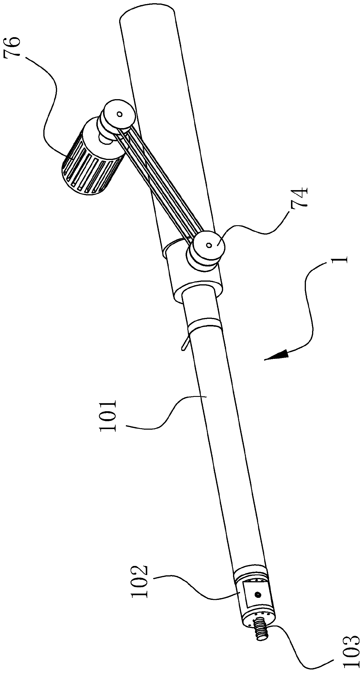
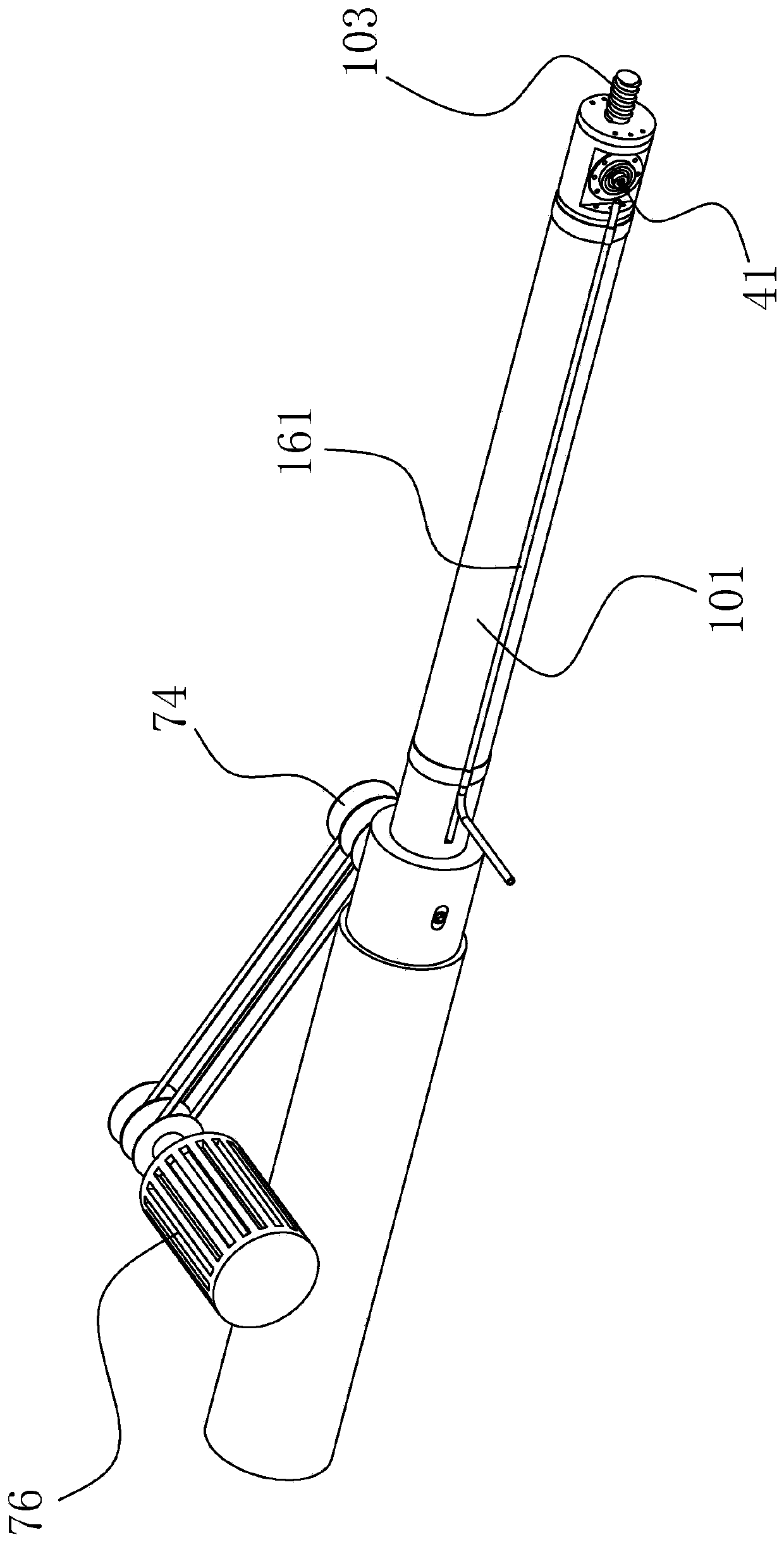
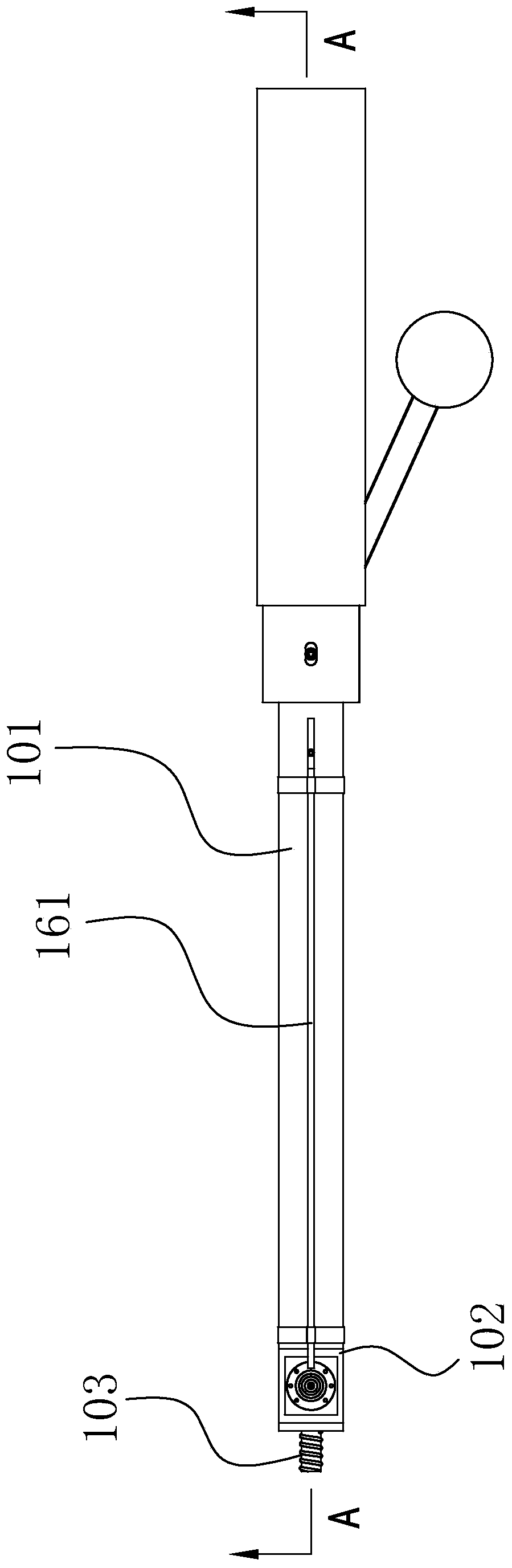
[0031] Such as Figure 1 to Figure 15Shown, the milling cutter structure that is used for machine barrel inner hole milling groove of the present embodiment comprises the cutter head 41 that is used for machine barrel inner hole milling groove, the rotating part that can detach type fixed cutter head 41, can connect with the drive motor The transmission part linked with the output shaft and the cutter bar 1 that can extend into the inner hole of the barrel, the rotating part is rotatably arranged on the head of the cutter bar 1, and the transmission part is arranged at the rear part of the cutter bar 1. The axial direction of 1 is provided with a cavity 11 that can be put into the transmission belt 12. The rotating part is linked with the transmission part through the transmission belt 12. When the milling cutter is working, the cutter head 41...


PUM


Abstract

The invention discloses a milling cutter structure for cylinder inner hole groove milling. The milling cutter structure comprises a cutter head for milling a groove in an inner hole of a cylinder, a rotating part capable of detachably fixing a tool bit, a transmission part capable of being linked with an output shaft of a driving motor, and a cutter bar capable of extending into the inner hole ofthe cylinder. The rotating part is rotatably arranged at the head part of the cutter bar; the transmission part is arranged at the rear part of the cutter bar; a cavity capable of containing a transmission belt is formed in the cutter bar in the axial direction; the rotating part is in linkage with the transmission part through the transmission belt; when the milling cutter works, the tool bit canmake contact with the inner wall of the cylinder along with movement of the cutter bar in the inner hole of the cylinder to rotate; and a conveying pipe capable of conveying cooling water to the cutter bit is arranged on the cutter bar in the axial direction. The milling cutter structure has the advantages that the groove penetrating through the inner hole of the cylinder can be milled in the inner wall of the inner hole of the cylinder; the tool bit is convenient to replace after being abraded; a spiral groove can be machined in the inner hole of the cylinder; and the groove milling depth ofthe tool bit on the inner wall of the inner hole of the cylinder can be changed.

Description

technical field [0001] The invention relates to the technical field of slot milling cutter manufacturing, in particular to a milling cutter structure for milling slots in inner holes of machine barrels. Background technique [0002] An existing Chinese utility model patent with the application number CN200920062482.8 titled "A Four-Edge End Mill Slot Knife" discloses a four-blade end mill slot cutter, which is mainly composed of a blade body and a blade, and is characterized in that the blade has 4 cutting edges, compared with 2 cutting edges, 4 cutting edges have 2 more cutting edges, so the milling efficiency is improved. Under the same rotation speed and the same cutting speed, 4 cutting edges are less likely to miss milling The groove surface and the groove are smoother, which has the advantages of high production efficiency and high processing precision. However, the milling cutter is usually connected to the rotating mechanism to mill the groove on the surface of the ...

Claims


Application Information

Patent Timeline
Patent Type & Authority Applications(China)
IPC IPC(8): B23C5/00B23C5/22B23C5/28B23C3/32B23C9/00B23Q5/10
CPCB23C3/32B23C5/00B23C5/2204B23C5/28B23C9/00B23C2210/168B23C2210/40B23Q5/10
Inventor 周立权
Owner 舟山市金塘山舟机械厂
Why Eureka
Try Eureka