Pipe cut-off machine with automatic clamping mechanism

A technology of automatic clamping and clamping mechanism, applied in the field of machining, can solve the problems of low production efficiency, low safety performance, poor cutting effect, etc., and achieve the effect of good clamping stability, high safety factor, and convenient storage.

Active Publication Date: 2020-04-10
山东金润德新材料科技股份有限公司
View PDF9 Cites 11 Cited by
  • Summary
  • Abstract
  • Description
  • Claims
  • Application Information

AI Technical Summary

Problems solved by technology

The current cutting machine has poor cutting effect, low safety performance, insufficient stability when

Method used


Image

  • Pipe cut-off machine with automatic clamping mechanism
  • Pipe cut-off machine with automatic clamping mechanism
  • Pipe cut-off machine with automatic clamping mechanism

Examples


Embodiment Construction

[0032] In order to clearly illustrate the technical features of the solution, the solution will be described below through specific implementation modes.

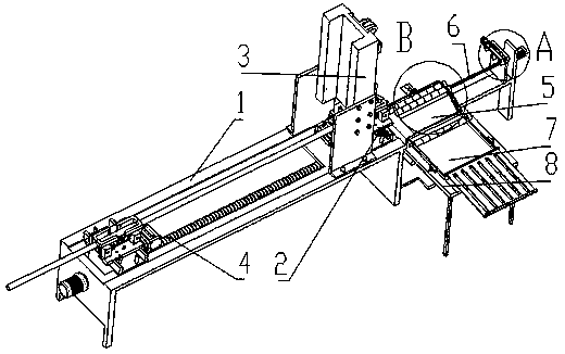
[0033] see Figure 1-Figure 10 , a pipe cutting machine with an automatic clamping mechanism, comprising a frame 1, a clamping mechanism 2 is fixedly arranged above one end of the frame 1, and a cutting mechanism 3 is arranged on the frame 1 and above the clamping mechanism 2;

[0034] The clamping mechanism 2 includes a base 201. The middle position of the base 201 is provided with a rotating shaft through rotation. Generally, a bearing is used. The upper end of the rotating shaft is rotated to be provided with a short connecting rod 213, which can be connected by a pin shaft. Both ends of the short connecting rod 213 are provided with The long connecting rod 215, the long connecting rod 215 is located below the short connecting rod 213; the short connecting rod 213 and the long connecting rod 215 can be connected by a pin...


PUM


Abstract

The invention provides a pipe cut-off machine with an automatic clamping mechanism, and belongs to the technical field of machining. According to the technical scheme, a clamping mechanism is fixedlyarranged on one end of a rack, and a cutting mechanism is arranged on the rack and located above the clamping mechanism; a rotating shaft is rotationally arranged in the middle of the base; a short connecting rod is rotationally arranged at the upper end of the rotating shaft; long connecting rods are rotationally arranged at the two ends of the short connecting rod and located under the short connecting rod; side plates are arranged on the two sides of the base; clamp bottom plates are arranged above the two side plates and located on the two sides of the short connecting rod in a sliding mode; the other ends of the long connecting rods are arranged on the clamp bottom plates in a rotating connection mode; mounting blocks are arranged on the clamp bottom plates; and clamping plates are symmetrically arranged on the inner sides of the two opposite mounting blocks; and the two clamp bottom plates are connected through a telescopic mechanism. The pipe cut-off machine has the beneficial effects that a pipe can be clamped, the clamping stability is good, and the safety coefficient is high.

Description

technical field [0001] The invention relates to the technical field of mechanical processing, in particular to a pipe cutting machine with an automatic clamping mechanism. Background technique [0002] Stainless steel pipe fittings are a general term for various stainless steel pipe connectors, which can be divided into different categories according to shape, purpose, and connection method. It has the characteristics of easy installation, high performance, environmental protection and durability, and is widely used in various pipeline construction and installation. In the production process, stainless steel pipe fittings need to be cut according to the corresponding length, which requires the use of a pipe cutting machine, and the clamping device of the cutting machine is its key component. The current cutting machine has poor cutting effect, low safety performance, insufficient stability when cutting the pipe fittings, often occurs the pipe fittings rotation or displaceme...

Claims


Application Information

Patent Timeline
IPC IPC(8): B23D21/00B23D33/02B23D33/00B23Q7/00
CPCB23D21/00B23D33/00B23D33/02B23Q7/00
Inventor 李家泉武万程郑王王珅
Owner 山东金润德新材料科技股份有限公司
Why Eureka
Try Eureka