Welding equipment for side-end steel plates and stacked welding method thereof

A welding equipment and welding method technology, applied in welding equipment, arc welding equipment, welding accessories, etc., can solve the problems of insufficient accuracy, inconvenient manual operation, lack of automation equipment, etc., to solve the problem of low work efficiency and guarantee Accuracy to ensure one-to-one correspondence

Active Publication Date: 2020-04-10
芜湖隆深机器人有限公司
View PDF9 Cites 0 Cited by
  • Summary
  • Abstract
  • Description
  • Claims
  • Application Information

AI Technical Summary

Problems solved by technology

[0002] Using the overlay welding method of argon arc welding, on the cast iron mold with chromium and nickel base materials, the method of quickly overlaying and welding a large punching die-cutting edge with high hardness requires mature manual work. , with the improvement of mechanization, more and more robots are used for welding, but the accuracy cannot meet the requirements
Especially when it is necessary to weld lateral steel plates, it is often inconvenient to operate manually. At present, there is also a lack of automatic equipment for welding lateral steel plates to make up for the shortcomings in actual production and processing.

Method used


Image

  • Welding equipment for side-end steel plates and stacked welding method thereof
  • Welding equipment for side-end steel plates and stacked welding method thereof
  • Welding equipment for side-end steel plates and stacked welding method thereof

Examples


Embodiment Construction

[0023] In order to make the technical means, creative features, objectives and effects of the present invention easy to understand, the present invention will be further explained below.

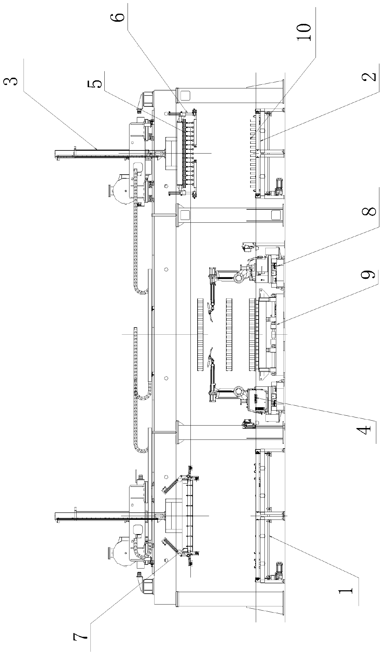
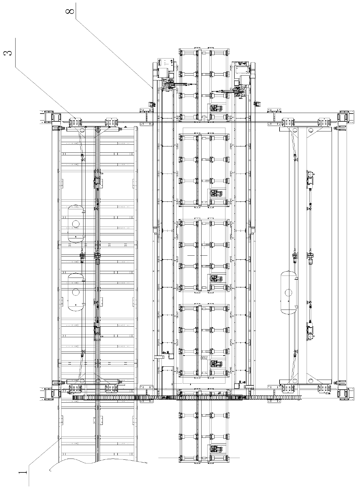
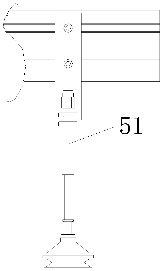
[0024] Such as Figure 1 to Figure 5 As shown, a welding equipment for side-end steel plates includes a top plate side plate conveying line for conveying the top plate and side plates 1, a core plate bottom plate conveying line for conveying core plates, and several groups of grippers for grabbing materials. The material manipulator 3 and the arc welding robot 4 for spot welding also include a core plate gripper 5 for grabbing the core plate and a top plate side plate grabbing device respectively arranged on the material grabbing manipulator 3 Tool 7. A fall prevention mechanism 6 arranged on the core board gripper 5 for placing the core board to fall.

[0025] The lower end of the welding station between the arc welding robots 4 is provided with a rolling bed 9 for quick replacement of welding ...


PUM


Abstract

The invention relates to the field of stacked welding, in particular to welding equipment for side-end steel plates and a stacked welding method thereof. The welding equipment for the side-end steel plates comprises a top plate and side plate conveying line used for conveying a top plate and a side plate, a core plate and a bottom plate conveying line used for conveying a core plate, a plurality groups of material gripping manipulators used for gripping materials and arc welding robots used for conducting spot welding; and the welding equipment for the side-end steel plates further comprises acore plate gripper which is arranged on the corresponding material gripping manipulator and used for gripping the core plate, a top plate and side plate gripper which is arranged on the correspondingmaterial gripping manipulator and used for gripping the top plate and the side plate and an anti-falling mechanism which is arranged on the core plate gripper and used for preventing the core plate from falling off. The stacked welding method comprises the following specific steps that 1, the core plate is put; 2, the side plate is put; and 3, spot welding is conducted. According to the welding equipment for the side-end steel plates and the stacked welding method thereof, the arc welding robots slide to conduct spot welding, spot welding is conducted on the top plate and the side plate and conducted on the side plate and the bottom plate, through cooperation with the core plate gripper and the top plate and side plate gripper which are provided with vacuum suction cups and used for sucking the core plate and the top plate, one plate can be gripped at a time, one-to-one correspondence of station beats is guaranteed, and the precision is guaranteed.

Description

Technical field [0001] The invention relates to the field of stack welding, in particular to a welding equipment for side end steel plates and a stack welding method thereof. Background technique [0002] The superposition welding method of argon arc welding is used to quickly superimpose and weld the chromium and nickel base cast iron molds into a large punching die cutting edge with high hardness. The existing technology requires mature manual work. With the improvement of mechanization, more and more robots are used for welding, but the accuracy is not up to the requirement. Especially when it is necessary to weld lateral steel plates, manual operation is often inconvenient. At present, there is also a lack of automatic equipment for welding lateral steel plates to make up for the shortcomings in actual production and processing. Summary of the invention [0003] In order to solve the above problems, the present invention proposes a welding equipment for side end steel plates ...

Claims


Application Information

Patent Timeline
IPC IPC(8): B23K9/007B23K9/32
CPCB23K9/007B23K9/32
Inventor 陈效陈家龙张壮壮
Owner 芜湖隆深机器人有限公司
Why Eureka
Try Eureka