A precision control method for electron beam welding deformation of rotor parts

A technology of electron beam welding and precision control, which is applied in the direction of electron beam welding equipment, welding equipment, manufacturing tools, etc., can solve the problems of low bolt connection process strength, poor part manufacturing compliance, and poor part adaptability, so as to improve design and manufacturing compliance. High performance, improved service life and low cost

Active Publication Date: 2021-10-29
SHENYANG LIMING AERO-ENGINE GROUP CORPORATION
View PDF7 Cites 0 Cited by
  • Summary
  • Abstract
  • Description
  • Claims
  • Application Information

AI Technical Summary

Problems solved by technology

Among them, the strength of the bolt connection process is relatively low, which will increase the weight of the engine; the inertial friction welding process has high equipment costs, complex tooling, and poor adaptability to parts; and the conventional electron beam welding process is difficult to meet the dimensional accuracy of new aero-engine rotor parts. Control requirements, resulting in poor part design and manufacturing compliance
[0004] The machining precision of rotor parts is high, and it is an ideal process to connect the rotors at all levels by electron beam welding. Due to the limitation of part structure and processing methods, the key parts such as webs and blades cannot be guaranteed by the method of reserve margin, while welding The existing inherent deformation often leads to the phenomenon that the size of the parts is out of tolerance

Method used


Image

  • A precision control method for electron beam welding deformation of rotor parts
  • A precision control method for electron beam welding deformation of rotor parts
  • A precision control method for electron beam welding deformation of rotor parts

Examples


Embodiment Construction

[0038] The present invention will be further described in detail below in conjunction with the accompanying drawings and embodiments.

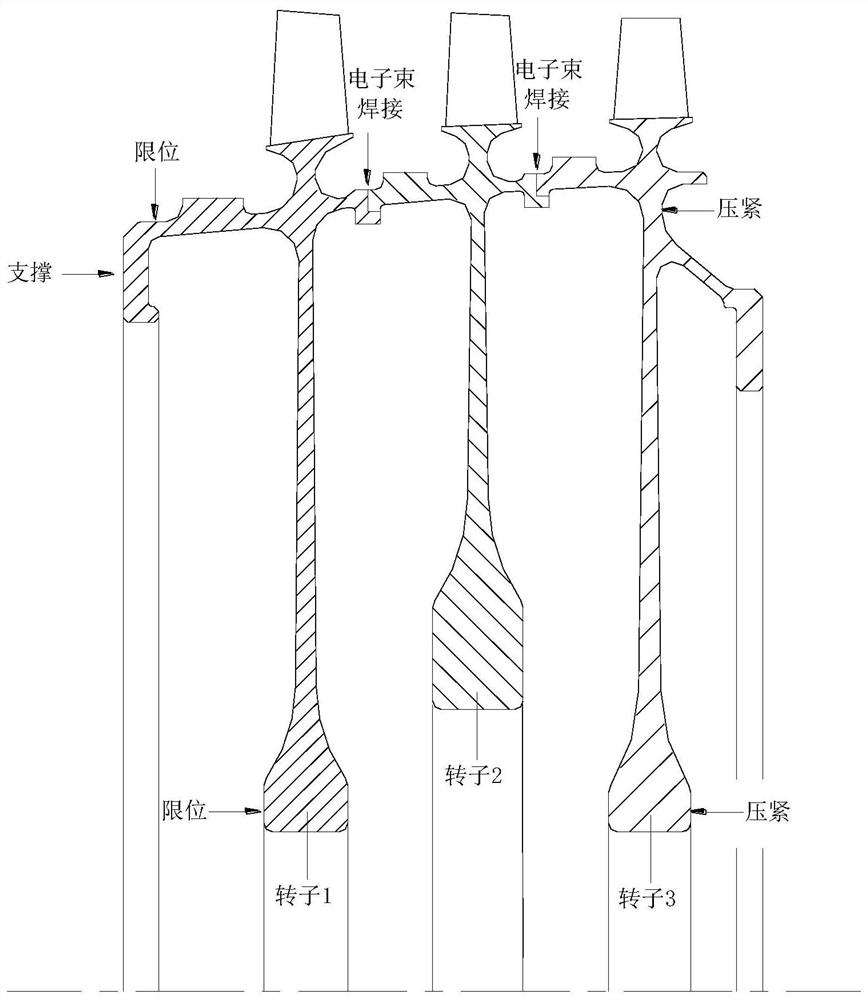
[0039] A precise control method for electron beam welding deformation of rotor parts. According to the structure of rotor parts and the characteristics of electron beam welding process, the causes of welding deformation are analyzed, and measures are taken from the following aspects to control welding deformation: 1) in the guarantee Under the premise of weld performance, adjust the pre-weld state of rotor parts from solid solution state to aging state, strengthen materials, improve the rigidity of rotor parts, and reduce welding deformation; 2) thin-walled cantilever for rotor parts structure, with the characteristics of large axial displacement after welding, the design of tooling with functions such as positioning, rigid limit and radial plate compression can reduce the axial displacement of the radial plate; The assembly and positioning ac...


PUM


Abstract

A precise control method for electron beam welding deformation of rotor parts, belonging to the technical field of electron beam welding of rotor parts, comprising the following steps: step 1: electron beam welding structure design; step 2: determination of electron beam welding parameters; step 3: Design of electron beam welding tooling; Step 4: Adjustment of material state of parts before welding; Step 5: Determination of welding shrinkage of parts; Step 6: Electron beam welding of rotor parts. According to the structural characteristics of rotor parts, this technology starts from the aspects of improving the rigidity of parts, rigidity fixation, reducing residual stress, and improving the uniformity of residual stress distribution, etc., and adopts corresponding technological measures to realize precise control of welding deformation by electron beam welding. There is a process, and the parts using this technology have high connection quality, low cost, wide process adaptability, and good deformation control effect.

Description

technical field [0001] The invention belongs to the technical field of electron beam welding of rotor parts, and in particular relates to a precise control method for electron beam welding deformation of rotor parts. Background technique [0002] With the development of the economy, there is more and more demand for aero-engines and gas turbines, and the manufacturing cost of rotor parts is extremely high. They are the core components of aero-engines, gas turbines and other power turbines. Welding is its key manufacturing technique. [0003] At present, the connection processes of aero-engine rotor parts include bolt connection, inertia friction welding connection and vacuum electron beam welding connection. Among them, the strength of the bolt connection process is relatively low, which will increase the weight of the engine; the inertial friction welding process has high equipment costs, complex tooling, and poor adaptability to parts; and the conventional electron beam w...

Claims


Application Information

Patent Timeline
Patent Type & Authority Patents(China)
IPC IPC(8): B23K15/00
CPCB23K15/0006B23K15/0026B23K15/0033B23K15/0053
Inventor 葛沁李英邵天巍曲伸宋文清
Owner SHENYANG LIMING AERO-ENGINE GROUP CORPORATION
Why Eureka
Try Eureka