
Laser die cutting machine and die cutting method

A die-cutting machine and laser cutting technology, used in laser welding equipment, welding equipment, metal processing equipment, etc., can solve problems such as affecting battery quality and poor accuracy, and achieve the goal of improving cutting accuracy, reducing tension fluctuations, and ensuring cutting accuracy. Effect

Active Publication Date: 2020-04-10
GUANGZHOU EHOLLY MACHINERY CO LTD
View PDF8 Cites 6 Cited by
  • Summary
  • Abstract
  • Description
  • Claims
  • Application Information

AI Technical Summary

Problems solved by technology

In the process of producing batteries, it is necessary to use a laser die-cutting machine to cut the pole pieces into different specifications and sizes, but the precision of traditional laser die-cutting machines for cutting pole pieces is poor, which affects the quality of the battery

Method used


Image

  • Laser die cutting machine and die cutting method
  • Laser die cutting machine and die cutting method
  • Laser die cutting machine and die cutting method

Examples


Embodiment Construction

[0049] In order to make the above objects, features and advantages of the present invention more comprehensible, specific implementations of the present invention will be described in detail below in conjunction with the accompanying drawings. In the following description, numerous specific details are set forth in order to provide a thorough understanding of the present invention. However, the present invention can be implemented in many other ways different from those described here, and those skilled in the art can make similar improvements without departing from the connotation of the present invention, so the present invention is not limited by the specific implementations disclosed below.

[0050] It should be noted that when an element is referred to as being “fixed” to another element, it can be directly on the other element or there can also be an intervening element. When an element is referred to as being "connected to" another element, it can be directly connected ...


PUM


Abstract

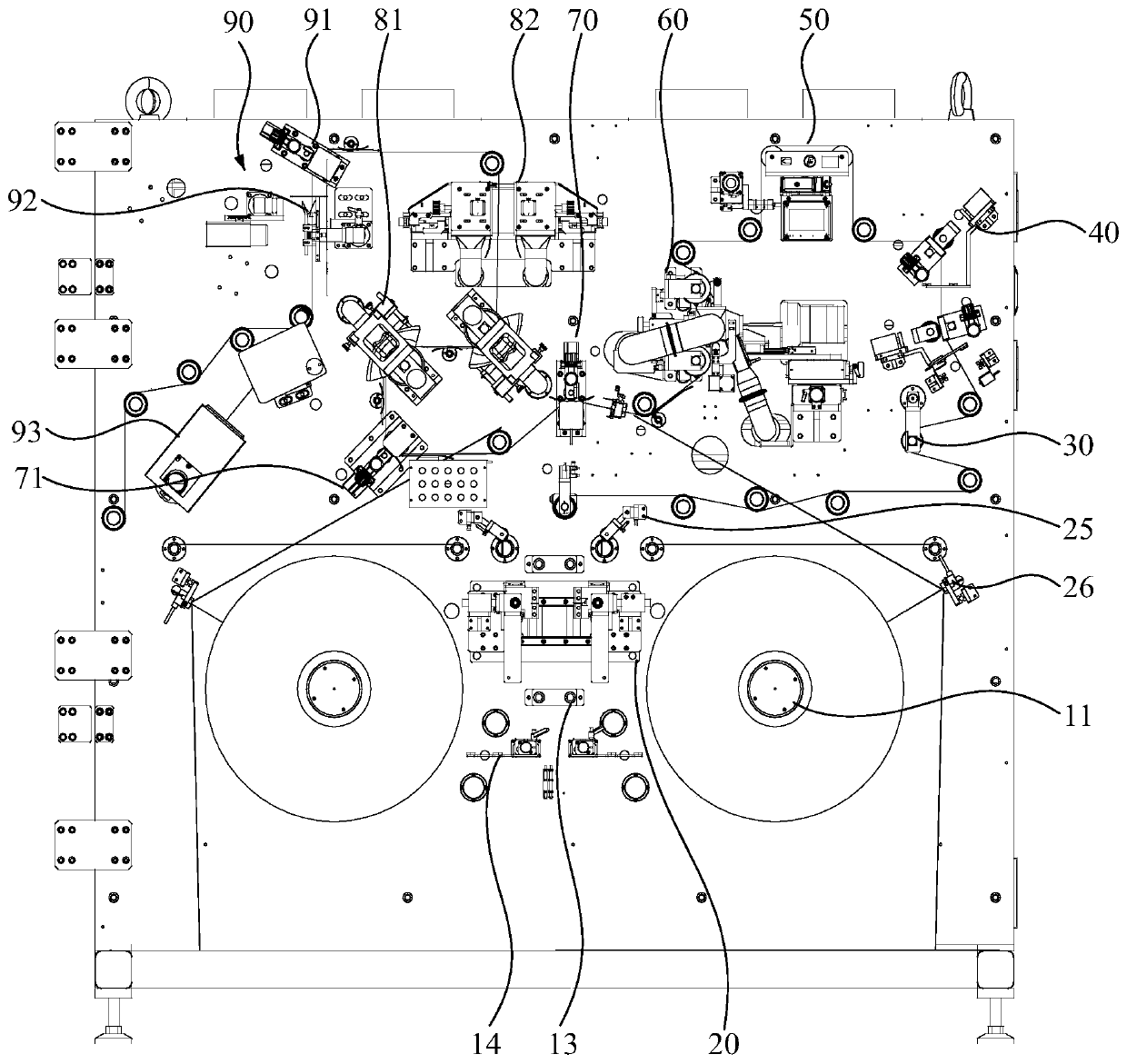
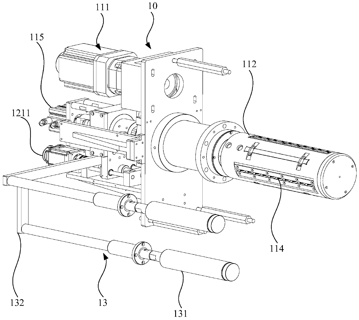
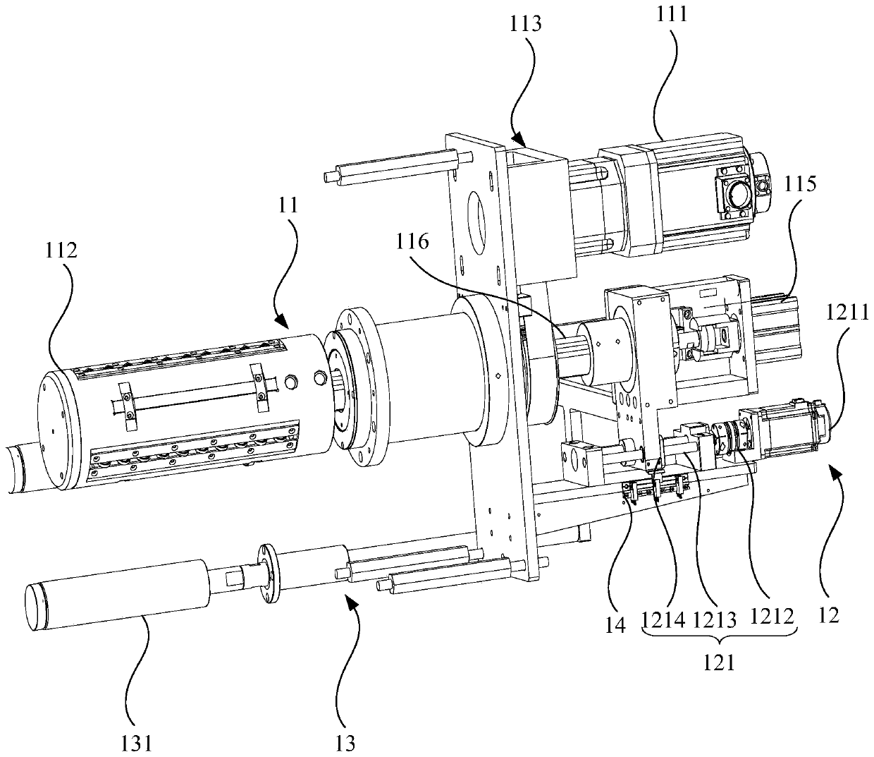
The invention relates to a laser die cutting machine and a die cutting method. The laser die cutting machine comprises an unwinding device, a tension control mechanism and a laser cutting mechanism. The unwinding device comprises an unwinding mechanism, an unwinding rectifying mechanism, a rectifying auxiliary mechanism and a rectifying detecting piece for detecting if materials are deviated; theunwinding rectifying mechanism comprises a first moving module; the unwinding mechanism and the rectifying auxiliary mechanism are connected with the unwinding rectifying mechanism; and the first moving module can drive the unwinding mechanism and the rectifying auxiliary mechanism to move. The tension control mechanism is used for adjusting the tension of the materials to maintain constant tension of the materials. The unwinding device, the tension control mechanism and the laser cutting mechanism are arranged in a material conveying direction. The laser die cutting machine can rectify polarpieces, and meanwhile, reduces the tension fluctuation of the polar pieces in the conveying process to improve the cutting precision of the polar pieces.

Description

technical field [0001] The invention relates to the technical field of battery manufacturing, in particular to a laser die-cutting machine and a die-cutting method. Background technique [0002] Traction battery is a power source that provides power source. It has the characteristics of high energy, high power, safety and reliability, and is widely used in vehicles, power systems and other fields. The battery cell is the smallest unit of the battery. The battery cell is usually composed of multiple winding cores connected in parallel. For the battery core of the winding power battery, the positive electrode sheet, the negative electrode sheet and the separator are usually wound by a winding machine according to a certain production process. made. In the process of producing battery cells, it is necessary to use a laser die-cutting machine to cut the pole pieces into different specifications and sizes, but the precision of traditional laser die-cutting machines for cutting p...

Claims


Application Information

Patent Timeline
Patent Type & Authority Applications(China)
IPC IPC(8): B23K26/38B23K26/08B23K26/16B23K26/70
CPCB23K26/0853B23K26/16B23K26/38B23K26/702
Inventor 张权王刚
Owner GUANGZHOU EHOLLY MACHINERY CO LTD
Learn More