Semi-automatic sandblasting device

A sandblasting device, a semi-automatic technology, is applied to explosion generating devices, used abrasive treatment devices, spray guns, etc. It can solve the problems of long time required, uneven surface treatment of products, etc., and achieve good effect and sandblasting effect. Good, regular and beautiful effect on the surface of the tank

Active Publication Date: 2020-11-06
安徽元通水处理设备有限公司
View PDF3 Cites 0 Cited by
  • Summary
  • Abstract
  • Description
  • Claims
  • Application Information

AI Technical Summary

Problems solved by technology

Realize large-scale popularization and application in the field of sandblasting; solve the problem that the existing equipment mainly consists of a booster pump with a sandblasting gun, which can only be operated by a single person. Uniform Technical Issues

Method used


Image

  • Semi-automatic sandblasting device
  • Semi-automatic sandblasting device
  • Semi-automatic sandblasting device

Examples


Embodiment 2

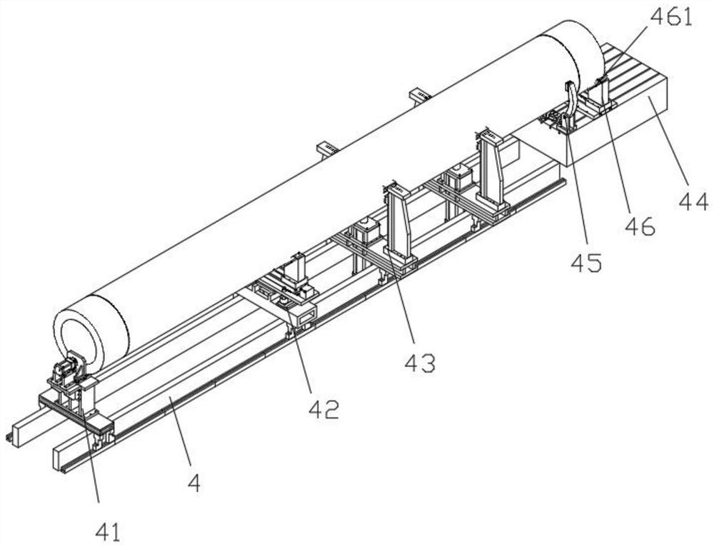
[0049] The working steps of the semi-automatic sandblasting device are:

[0050] Step 1. Drive cylinder 5 451, push the two arc-shaped plates 453 to move inward through the piston rods at both ends, until the fourth scraper 454 contacts the surfaces on both sides of the tank body, and the arc-shaped plates 453 are used to support the tank body function, the fourth scraper 454 is used to scrape sand on its surface; then drive the cylinder three 431 to push the lifting block 436 up, and drive two cylinder four 434 at the same time, and the two cylinder four 434 push the two movable blocks 435 to rotate to form a V Shaped structure, two movable blocks 435 are in contact with the bottom surface of the tank body, the two movable blocks 435 and the side plates 433 are used to support the tank body, and the third scraper 437 is in contact with the surface on both sides of the tank body; finally drive the cylinder Six 423, push the lifting seat 429 up and down, then drive the servo mo...


PUM


Abstract

The invention discloses a semi-automatic sand blasting device. The device comprises an operation table, a vertical plate, a transverse plate, mounting strips and sand blasting guns, wherein the vertical plate is fixedly mounted on the top of the operation table, the transverse plate is fixedly mounted on the top of the vertical plate, a first servo motor is fixedly mounted at one end of the top ofthe transverse plate, an output shaft of the first servo motor is connected with a first screw rod through a coupling, and the first screw rod is connected with a second servo motor through a first sliding block. Through the arrangement of a groove, a first cylinder and clamping plates, a tank body is fixed, and thus the inconvenience caused by manual fixing of the tank body is avoided; meanwhile, it is convenient for a rotating motor to drive the tank body to rotate, the sand blasting is more uniform, the sand blasting effect is better, tank bodies with different sizes are convenient to fix,and use is convenient; and through the arrangement of a push plate and a second cylinder, the inconvenience of the operation of manually pushing the tank body to move is avoided.

Description

technical field [0001] The invention relates to the technical field of sand blasting devices, in particular to a semi-automatic sand blasting device. Background technique [0002] As the market's requirements for product quality are getting higher and higher, the workpieces produced by the original manual sandblasting equipment can no longer meet the needs of today's market. And work efficiency and its low, make product can't batch production. In the past, the sandblasting equipment mainly consisted of a booster pump with a sandblasting gun, which could only be operated by a single person. It took a long time to sandblast products, and the surface treatment of the products was uneven, which made it difficult to satisfy customers; and The existing sandblasting device can only blast the tank body with a single diameter and length, which is poor in practicability, inconvenient to operate, and cannot scrape sand on the surface of the tank body to make the sandblasting more unif...

Claims


Application Information

Patent Timeline
Patent Type & Authority Patents(China)
IPC IPC(8): B24C3/02B24C5/02B24C9/00
CPCB24C3/02B24C5/02B24C9/00
Inventor 赵蒙蒙王勇郝剑
Owner 安徽元通水处理设备有限公司
Why Eureka
Try Eureka