
Sandwich heat preservation composite shear wall prefabricated part and manufacturing method thereof

A technology of superimposing shear walls and prefabricated components, applied in thermal insulation, building components, walls, etc., can solve the problems of cracking of outer leaf concrete wall panels, unclear force on connectors, unclear design calculation, etc. The force is not clear, the design calculation is not clear, and the force is reasonable.

Pending Publication Date: 2020-04-10
CABR TECH CO LTD
View PDF0 Cites 7 Cited by
  • Summary
  • Abstract
  • Description
  • Claims
  • Application Information

AI Technical Summary

Problems solved by technology

[0007] The purpose of the present invention is to provide a new type of sandwich insulation composite shear wall prefabricated component, which solves the unclear stress and design calculation of traditional connectors by using a connector system formed by independent truss connectors and rod connectors In order to avoid the combination effect of the wall due to the strong constraints of the connectors, which will cause cracking and deformation of the outer leaf concrete wall panels, the structure of the sandwich insulation laminated shear wall is more reasonable, and the stress mode is more in line with design expectations.

Method used


Image

  • Sandwich heat preservation composite shear wall prefabricated part and manufacturing method thereof
  • Sandwich heat preservation composite shear wall prefabricated part and manufacturing method thereof
  • Sandwich heat preservation composite shear wall prefabricated part and manufacturing method thereof

Examples


Embodiment Construction

[0036] In order to make the technical scheme of the present invention easy to understand, it is further described as follows in conjunction with the accompanying drawings:

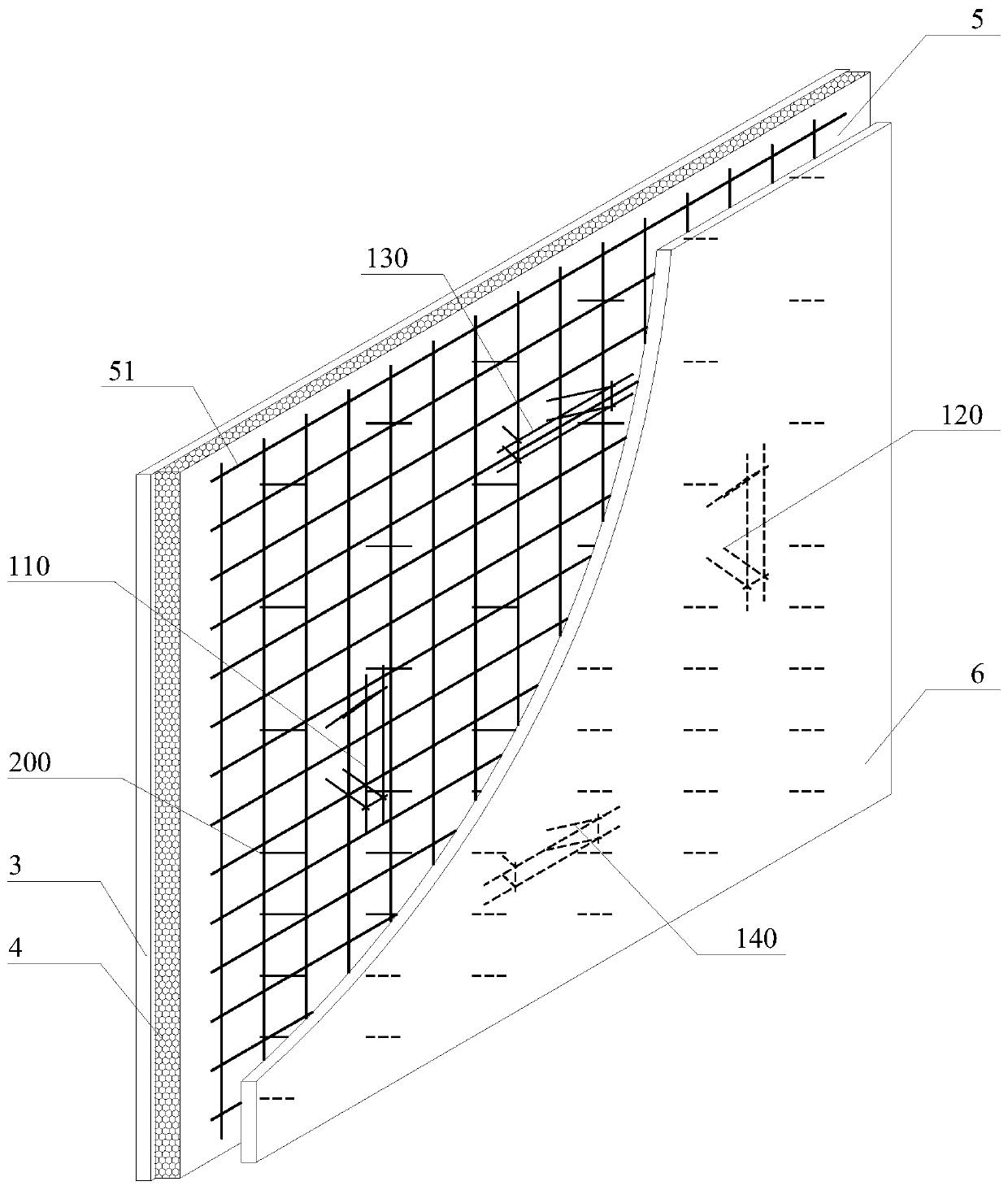
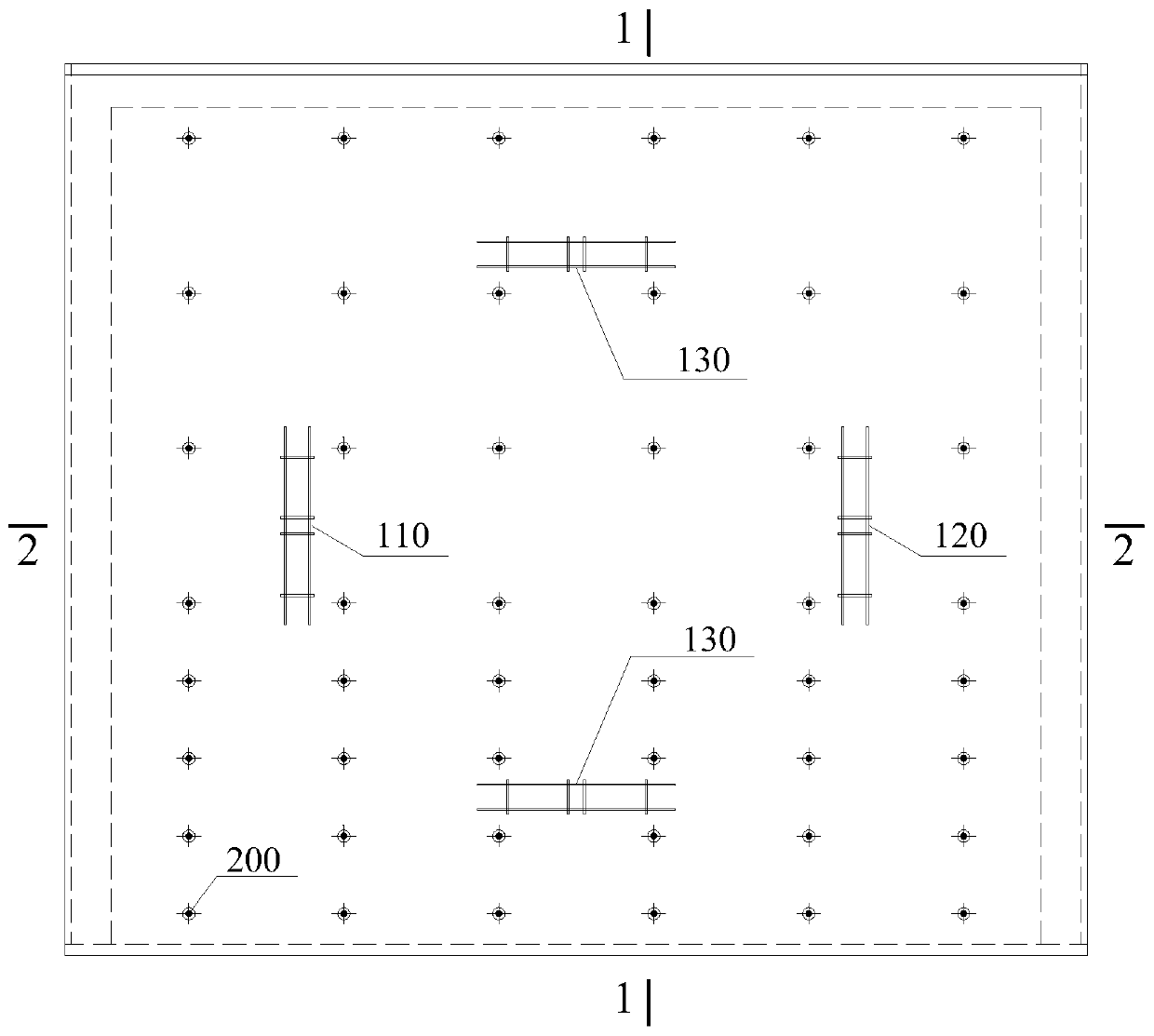
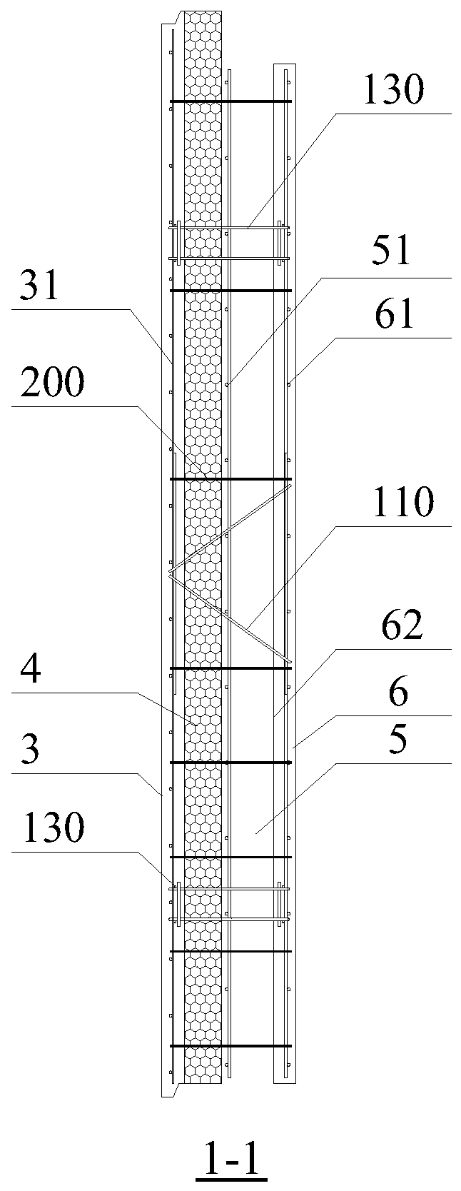
[0037] see Figure 1~4 (It should be noted that in order to reflect the layout of the connector system more clearly, figure 1 The steel mesh sheet in the inner leaf concrete wall panel and the outer leaf concrete wall panel is not shown in the figure), a sandwich insulation laminated shear wall prefabricated component proposed by the present invention includes outer leaves arranged in sequence along the thickness direction of the shear wall Concrete wall panel 3, insulation layer 4, cavity 5 and inner leaf concrete wall panel 6, and a connector system for connecting inner and outer leaf concrete wall panels, the connector system extending through cavity 5 and insulation layer 4 In the inner and outer leaf concrete wall panels, the connector system includes at least four independent truss connectors (110, ...


PUM

PropertyMeasurementUnit
diameteraaaaaaaaaa
diameteraaaaaaaaaa

Abstract

The invention discloses a sandwich heat preservation composite shear wall prefabricated part and a manufacturing method thereof. The prefabricated part comprises an inner concrete wallboard, an outerconcrete wallboard, a heat preservation layer, a cavity and a connecting piece system; the connecting piece system penetrates through the cavity and the heat preservation layer and extends into the inner concrete wallboard and the outer concrete wallboard; and the connecting piece system comprises at least four independent truss connecting pieces and a plurality of rod-shaped connecting pieces with the lengths distributed in a wall thickness direction. The manufacturing method comprises the following steps of: binding the reinforcing mesh of the outer concrete wallboard, and mounting the connecting piece system on the reinforcing mesh; pouring outer wallboard concrete, laying a heat insulation board, and mounting a reinforcing mesh in the cavity; binding and mounting the reinforcing mesh of the inner concrete wallboard, pouring concrete, keeping the inner concrete wallboard still, and integrally overturning other components by 180 degrees; and moving the overturned components towards the inner concrete wallboard, pressing the end portions of all the connecting pieces into the inner concrete wallboard and making the end portions of all the connecting pieces fully contact with the inner concrete wallboard. All components in the connecting piece system are stressed definitely, and the non-combined stress mode of a sandwich heat preservation composite shear wall is achieved.

Description

technical field [0001] The invention relates to the technical field of sandwich thermal insulation shear walls, in particular to sandwich thermal insulation laminated shear walls, in particular to an independent truss connector composed of outer leaf concrete wall panels, thermal insulation layers, cavities and inner leaf concrete wall panels The sandwich thermal insulation composite shear wall prefabricated component and its manufacturing method. Background technique [0002] At present, in my country's prefabricated shear wall structure system, the laminated shear wall components with cavities formed by the connection of two layers of concrete wall panels are used more and more. They are transported to the construction site and installed in place. Adjacent members behind the cavity concrete are connected to form a laminated shear wall, which has a simple connection structure and is convenient for construction. The laminated shear wall with sandwich insulation is a new type...

Claims


Application Information

Patent Timeline
Patent Type & Authority Applications(China)
IPC IPC(8): B28B1/04B28B23/02E04B1/76E04B2/56
CPCB28B1/045B28B23/02E04B1/76E04B2/56
Inventor 周剑田春雨
Owner CABR TECH CO LTD
Learn More