Efficient nap removal equipment for textile printing and dyeing

A high-efficiency technology for textile printing and dyeing, which is applied in the field of high-efficiency depilation equipment for textile printing and dyeing. It can solve the problems of polluting the surrounding environment and sanitation, narrow adaptation range, and random fluff flying, so as to avoid the influence of impurities, good dust removal effect, and improve printing and dyeing quality. Effect

Inactive Publication Date: 2020-04-10
莫永献
View PDF10 Cites 8 Cited by
  • Summary
  • Abstract
  • Description
  • Claims
  • Application Information

AI Technical Summary

Problems solved by technology

[0004] The purpose of the present invention is to provide a high-efficiency hair removal equipment for textile printing and dyeing, to solve the problem that the artificial hair removal proposed in the above background technology generally cannot remove dander thoroughly, and it is difficult to achieve the ideal effect of removi

Method used


Image

  • Efficient nap removal equipment for textile printing and dyeing
  • Efficient nap removal equipment for textile printing and dyeing
  • Efficient nap removal equipment for textile printing and dyeing

Examples


Embodiment Construction

[0024] The following will clearly and completely describe the technical solutions in the embodiments of the present invention with reference to the accompanying drawings in the embodiments of the present invention. Obviously, the described embodiments are only some, not all, embodiments of the present invention. Based on the embodiments of the present invention, all other embodiments obtained by persons of ordinary skill in the art without creative efforts fall within the protection scope of the present invention.

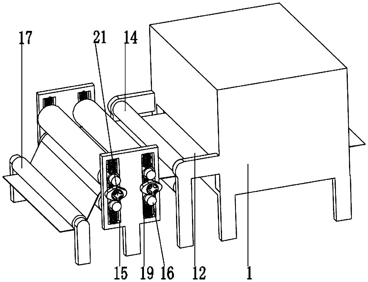
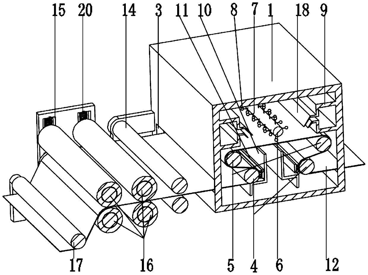
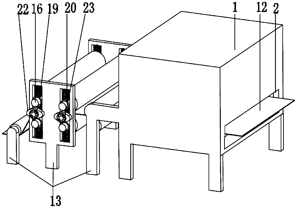
[0025] see Figure 1-3 , the present invention provides a technical solution:

[0026] A high-efficiency hair removal device for textile printing and dyeing, comprising a rough dust removal part and a fine dust removal part, the coarse dust removal part includes a dust removal box 1, the two side walls of the dust removal box 1 are respectively provided with a material inlet 2 and a material outlet 3, and the middle of the dust removal box 1 Rotationally connected...


PUM


Abstract

The invention discloses efficient nap removal equipment for textile printing and dyeing in the technical field of textile equipment. The efficient nap removal equipment for textile printing and dyeingcomprises a coarse dust removal part and a fine dust removal part, wherein the coarse dust removal part comprises a dust removal box; a group of inward collection compressing rollers and a group of flat laying rollers are rotationally connected in the middle of the dust removal box; a dust slapping roller is rotationally connected in the middle of the dust removal box; the side wall of the dust slapping roller is fixedly connected with a plurality of connecting ropes; the end part of each connecting rope is fixedly connected with a dust slapping ball; the two side walls and the bottom of thedust removal box are respectively and fixedly connected with side wall dust suction boxes and a bottom dust suction box; the fine dust removal part comprises an outside support frame; a middle conveying roller is rotationally connected in the middle of the outside support frame; a slide frame is arranged on the side wall of the outside support frame; dust sticking rollers are glidingly connected inside the slide frame; a holding assembly is fixedly connected between the dust sticking rollers and the slide frame; a switching assembly is rotationally arranged between the dust sticking rollers; and a maintaining roller is rotationally connected in the middle of the outside support frame. The efficient nap removal equipment has the advantages that the dust removal effect is good; the dust removal box performs sealed dust removal and cannot influence the outside environment; twice dust removal is performed, so that the effect is good; the influence by impurities is avoided; and the printingand dyeing quality is improved.

Description

technical field [0001] The invention relates to the technical field of textile equipment, in particular to a high-efficiency hair removal equipment for textile printing and dyeing. Background technique [0002] With the rapid development of China's economy, people's living standards are getting better and better, and people's spending power is also constantly increasing. Clothes are one of the main consumer goods in people's daily life. Cloths need to be dyed before they are made into clothes. , Clothes of different colors can meet the needs of people with different personalities and hobbies. Textile printing machines can print patterns on textiles; at present, printing machines can print a variety of fabrics well to achieve various effects, usually there will be some dander on the fabric, and these dander will affect The entire printing effect affects the quality of the product. However, most of the general printing machines do not have corresponding hair removal devices, ...

Claims


Application Information

Patent Timeline
IPC IPC(8): D06G1/00B08B7/00
CPCB08B7/0028D06G1/00
Inventor 莫永献
Owner 莫永献
Why Eureka
Try Eureka