A rainwater recovery and reuse device for buildings
A rainwater collection and building technology, applied in drinking water installations, water supply installations, buildings, etc., can solve problems such as high water pressure, and achieve the effect of relieving urban water pressure and avoiding safety accidents.
- Summary
- Abstract
- Description
- Claims
- Application Information
AI Technical Summary
Problems solved by technology
Method used
Image

Examples
specific Embodiment approach 1
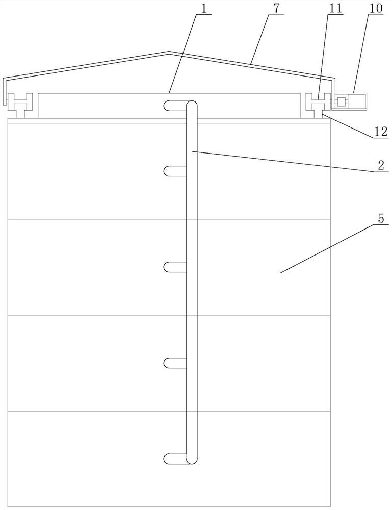
[0020] Specific implementation mode one: combine Figure 1 to Figure 7 This embodiment is described. The rainwater recycling device for buildings described in this embodiment includes a rainwater collection tank 1, a main pipe 2, an overflow prevention pipe 3, an overflow valve 4, a rain-shielding mechanism and a plurality of indoor storage tanks. The water mechanism, the rainwater collection tank 1 is fixedly installed on the top of the building body 5, the inlet of the main pipe 2 is connected with the outlet of the rainwater collection tank 1, and each resident room in the building body 5 is equipped with an indoor water storage system. mechanism, the inlet of each indoor water storage mechanism is connected to the outlet of the main pipeline 2 through a pipeline, the inlet of the overflow prevention pipeline 3 is connected to the overflow of the rainwater collection tank 1, and the overflow valve 4 is installed in the overflow prevention pipeline 3, the rain-shielding mech...
specific Embodiment approach 2
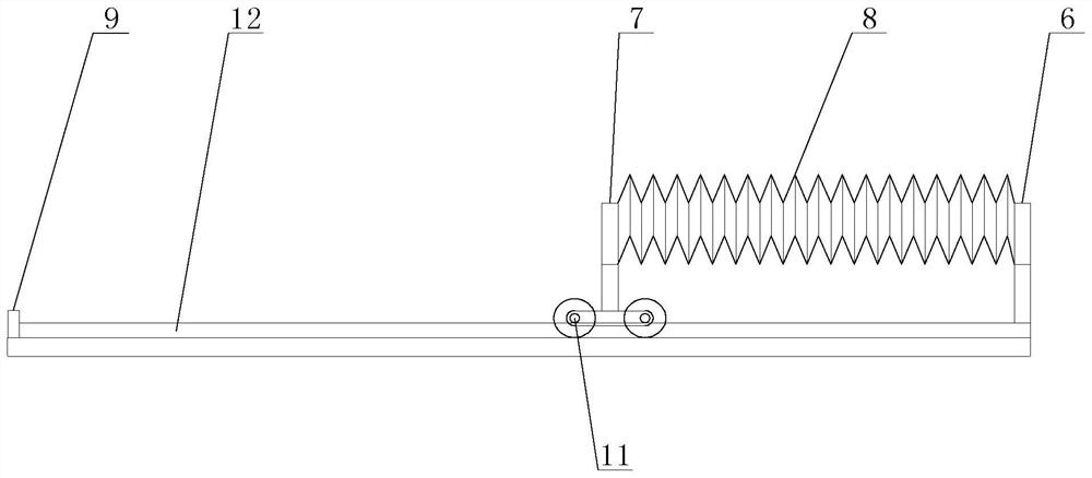
[0022] Specific implementation mode two: combination Figure 1 to Figure 7 Describe this embodiment, the rain-shielding mechanism of a kind of rainwater recycling and reuse device for a building body described in this embodiment includes a fixed bracket 6, a movable bracket 7, a rainproof cloth 8, a start switch assembly, a travel switch 9, a drive mechanism 10, Two mobile trolleys 11 and two tracks 12, the two tracks 12 are installed side by side on both sides of the rainwater collection tank 1, the two ends of the fixed support 6 are fixedly connected with the ends of the two tracks 12 respectively, and the two ends of the movable support 7 Through two mobile trolleys 11 and two rails 12 sliding connection, the driving mechanism 10 is installed on the mobile trolley 11, the fixed support 6 is connected with the movable support 7 through the rainproof cloth 8, and the rainproof cloth 8 can cover the groove of the rainwater collection tank 1 after being unfolded The travel swi...
specific Embodiment approach 3
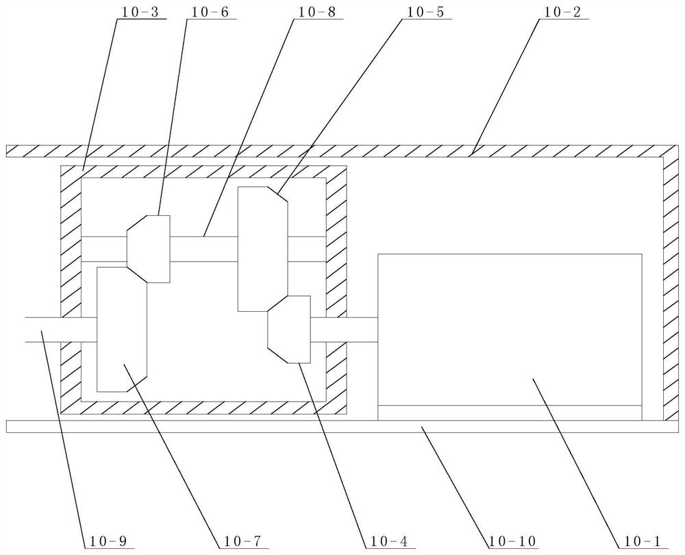
[0026] Specific implementation mode three: combination Figure 1 to Figure 7 Describe this embodiment, the driving mechanism 10 of a rainwater recovery and reuse device for buildings described in this embodiment includes a driving motor 10-1, a reduction box 10-3, a driving pinion 10-4, and a driving gear 10 -5, driven pinion gear 10-6, driven large gear 10-7, power transmission shaft 10-8, output shaft 10-9 and base plate 10-10, base plate 10-10 is horizontally set, and base plate 10-10 and mobile The trolley 11 is fixedly connected, the driving motor 10-1 and the reduction box body 10-3 are sequentially arranged on the bottom plate 10-10 from the outside to the inside, the transmission shaft 10-8 is installed in the reduction box body 10-3, and the driving gear 10- 5 and the driven pinion 10-6 are fixedly set on the transmission shaft 10-8, one end of the output shaft 10-9 is connected with the wheel shaft of the mobile trolley 11, and the other end of the output shaft 10-9 ...
PUM
 Abstract
Description
Claims
Application Information
 - R&D
- Intellectual Property
- Life Sciences
- Materials
- Tech Scout
- Unparalleled Data Quality
- Higher Quality Content
- 60% Fewer Hallucinations
Browse by: Latest US Patents, China's latest patents, Technical Efficacy Thesaurus, Application Domain, Technology Topic, Popular Technical Reports.
© 2025 PatSnap. All rights reserved.Legal|Privacy policy|Modern Slavery Act Transparency Statement|Sitemap|About US| Contact US: help@patsnap.com