
Mixing and discharging multifunctional pipeline system

A pipeline system and multi-functional technology, applied in the field of mixed multi-function pipeline system, can solve the problem of the whole line being unusable, and achieve the effect of ensuring continuity

Inactive Publication Date: 2020-04-10
中石化四机石油机械有限公司 +2
View PDF14 Cites 0 Cited by
  • Summary
  • Abstract
  • Description
  • Claims
  • Application Information

AI Technical Summary

Problems solved by technology

[0002] In the field of oil and natural gas production, the mixed flow device is the core equipment in fracturing construction. The existing mixed flow device mostly adopts a single-line production system, that is, a mixed flow is equipped with a manifold. There is a problem with the mixing device, which makes the whole line unusable

Method used


Image

  • Mixing and discharging multifunctional pipeline system
  • Mixing and discharging multifunctional pipeline system
  • Mixing and discharging multifunctional pipeline system

Examples


Embodiment Construction

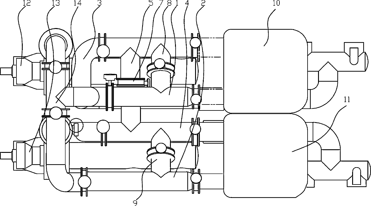
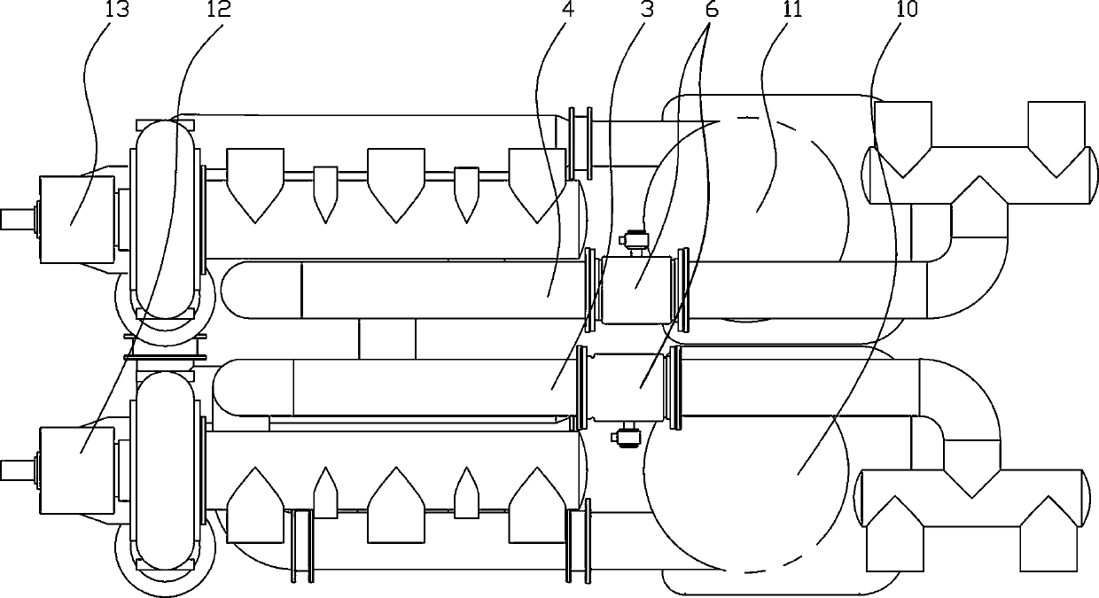
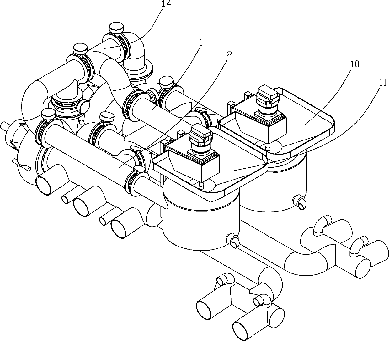
[0027] Such as Figure 1~4 Among them, a multifunctional pipeline system for mixed drainage, including a first mixed drainage access pipeline 1, a first mixed drainage outlet pipeline 3, a second mixed drainage inlet pipeline 2 and a second mixed drainage outlet pipeline 4 , Between the first mixed discharge outlet pipeline 3 and the second mixed discharge outlet pipeline 4, an outlet connecting pipe 5 is provided, and a valve member 7, such as a butterfly valve 707, is provided on the outlet connecting pipe 5. The valve parts are electronically controlled or hydraulically controlled valve parts. The valve element 7 in this example is preferably a butterfly valve. Electric or hydraulic control butterfly valves facilitate automatic or remote switching operations. With this structure, when a problem occurs in one outlet pipeline, one outlet pipeline can be switched to two mixing devices, or different discharge directions can be switched.

[0028] The preferred solution is as ...


PUM


Abstract

The invention provides a mixing and discharging multifunctional pipeline system. The mixing and discharging multifunctional pipeline system includes a first mixing and discharging inlet pipeline, a first mixing and discharging outlet pipeline, a second mixing and discharging inlet pipeline and a second mixing and discharging outlet pipeline. A connection pipe between outlets is arranged between the first mixing and discharging outlet pipeline and the second mixing and discharging outlet pipeline, and valves are arranged on the connection pipe between the outlets. According to a preferred scheme, and the valve parts are electrically controlled or hydraulically controlled valves. The valves are butterfly valves. The mixing and discharging multifunctional pipeline system can realize multi-path work, for example, by operating the corresponding valves, a plurality of liquid suction and discharging methods such as left suction and left discharging, left suction and right discharging, right suction and right discharging, right suction and left discharging, one suction and double discharging, double suction and one discharging and by-pass manifold without mixing and discharging devices canbe realized, and the connection and placement in a well site of a sand mixing truck during fracturing operation are convenient. It is further convenient to maintain the functions of other parts whensome parts need maintenance, and the continuity of work can be ensured.

Description

technical field [0001] The invention relates to the field of oil drilling and production equipment, in particular to a mixed-row multifunctional pipeline system. Background technique [0002] In the field of oil and natural gas production, the mixed flow device is the core equipment in fracturing construction. The existing mixed flow device mostly adopts a single-line production system, that is, a mixed flow is equipped with a manifold. A problem with the shuffling unit rendered the entire line unusable. For example, the Chinese patent document CN103343679B, an electro-hydraulic hybrid driving sand mixing vehicle, and CN103912259A, an electric driving sand mixing vehicle, all have the above-mentioned problems. Contents of the invention [0003] The technical problem to be solved by the present invention is to provide a mixed-drainage multi-functional pipeline system, which can retain some functions when some components fail, so as to achieve higher fault tolerance, ensure...

Claims


Application Information

Patent Timeline
Patent Type & Authority Applications(China)
IPC IPC(8): E21B43/26E21B43/267E21B34/02
CPCE21B34/02E21B43/26E21B43/267
Inventor 李龙杰尹进吴汉川彭平生李莉莉雷刚蔡正志边志英
Owner 中石化四机石油机械有限公司
Learn More